24VNA6: Installation Instructions
Manufacturer reserves the right to change, at any time, specifications and designs without notice and without obligations.
7
Final Tubing Check
IMPORTANT: Check to be certain factory tubing on both indoor and
outdoor unit has not shifted during shipment. Ensure tubes are not
rubbing against each other or any sheet metal. Pay close attention to
feeder tubes, making sure wire ties on feeder tubes are secure and tight.
Step 8 – Make Electrical Connections
Be sure field wiring complies with local and national fire, safety, and
electrical codes, and voltage to system is within limits shown on unit
rating plate. Contact local power company for correction of improper
voltage. See unit rating plate for recommended circuit protection device.
NOTE: Operation of unit on improper line voltage constitutes abuse and
could affect unit reliability. See unit rating plate. Do not install unit in
system where voltage may fluctuate above or below permissible limits.
NOTE: Use copper wire only between disconnect switch and unit.
NOTE: Install branch circuit disconnect of adequate size per NEC to
handle unit starting current. Locate disconnect within sight from and
readily accessible from unit, per Section 440-14 of NEC.
Route Ground and Power Wires
Remove access panel to gain access to unit wiring. Extend wires from
disconnect through power wiring hole provided and into unit control
box.
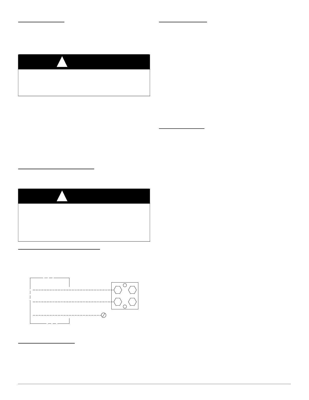
Connect Ground and Power Wires
Connect ground wire to ground connection in control box for safety.
Connect power wiring to contactor as shown in Fig. 9.
A14028
Fig. 9 – Line Power Connections
Connect Control Wiring
Connect to Infinity connections. Only two wires (AB) to Infinity
capable indoor unit (furnace or fan coil) is required. Typical 4 wire
(ABCD) may be connected (see Fig. 5)
IMPORTANT: This system requires the power supply to the outdoor
unit, and the indoor unit, for the UI to communicate with the outdoor
unit.
General Information
Use No. 18 AWG or larger color-coded, insulated (35°C minimum) wire
for low voltage control wires.
All wiring must be NEC Class 2 and must be separated from incoming
power leads.
Use furnace transformer, fan coil transformer, or accessory transformer
for control power requirement of system accessories external to the OD
unit. The outdoor unit has its own transformer power.
Installations using greater than 200 feet of low voltage wiring should
consult the Infinity wall control manual for additional guidelines
regarding daisy chaining wiring method and terminating resistors.
Never route control wiring in parallel to high voltage power wires when
possible as electrical noise may transfer and generate nuisance fault
codes. Where low voltage control and high voltage wires must cross
paths, do so at perpendicular angles to eliminate transferred noise.
If further communication issues exist, consider using shielded low
voltage wires and only connect shielding to C terminal at end nearest
indoor coil.
Final Wiring Check
IMPORTANT: Check factory wiring and field wire connections to
ensure terminations are secured properly. Check wire routing to ensure
wires are not in contact with tubing, sheet metal, etc.
Step 9 – Compressor Crankcase Heater
This compressor has a standard crankcase heater. Furnish power to the
unit a minimum of 24 hr before starting the unit for the first time.
To furnish power to heater only, set thermostat to OFF and close
electrical disconnect to outdoor unit.
Power is not required to the indoor unit or User Interface for proper
operation of heater. Crankcase heater will however be intelligently
energized as needed even when the UI and indoor unit is not installed, as
long as there is power to the outdoor unit even if the indoor unit and UI
are not yet installed.
Airflow Setup for Infinity Control Furnace or FE
Fan Coil (communicating)
This system can only be installed with Infinity-capable indoor and
Infinity System Control . When using an Infinity control, airflow is
automatically selected based on equipment size. The user has the option
of selecting Comfort, Efficiency and Max airflow for Cooling modes.
These should be selected based on balance between the homeowner’s
comfort and energy consumption expectations. See User Interface
Installation Instructions for additional available adjustments.
NOTE: Ensure control is updated with the latest available software
version.
Due to using a communicating control with the fan coil or the furnace,
dip switch adjustments are not necessary. The outdoor unit
configuration and the indoor airflows are determined by communicating
control setup.
Verify that the PCM, VFD and wall control are the latest software before
proceeding with the next steps.
Step 10 – Install Accessories
There are no refrigeration circuit or electrical accessories required or
available for installation within the unit. External to the unit, the same
accessories such as the liquid line solenoid, support feet, snow rack,
wind baffle etc., are available on other Carrier units can also be used on
this line of product. Refer to the individual Installation Instructions
packaged with kits or accessories when installing.
WARNING
!
ELECTRICAL SHOCK HAZARD
Failure to follow this warning could result in personal injury or death.
Do not supply power to unit with compressor terminal box cover
removed.
WARNING
!
ELECTRICAL SHOCK HAZARD
Failure to follow this warning could result in personal injury or death.
The unit cabinet must have an uninterrupted or unbroken ground to
minimize personal injury if an electrical fault should occur. The ground
may consist of electrical wire or metal conduit when installed in
accordance with existing electrical codes.
DISCONNECT
PER N. E. C. AND/OR
LOCAL CODES
TERMINAL
BLOCK
GROUND
LUG
FIELD GROUND
WIRING
FIELD POWER
WIRING
 Loading...