EasyManua.ls Logo

Carrier MMY-MAP0964FT6UL User Manual

Carrier MMY-MAP0964FT6UL
288 pages
To Next Page IconTo Next Page
Page #1 background imageLoading...
Page #1 background image
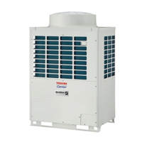
AIR CONDITIONER (MULTI TYPE)
SERVICE MANUAL
Outdoor Unit
< SUPER HEAT RECOVERY MULTI-i >
Model name:
MMY-MAP0724FT9UL
MMY-MAP0964FT9UL
MMY-MAP1204FT9UL
MMY-MAP0724FT6UL
MMY-MAP0964FT6UL
MMY-MAP1204FT6UL
Flow Selector Unit (FS unit)
Model name:
RBM-Y0383FUL
RBM-Y0613FUL
RBM-Y0963FUL
This service manual provides relevant explanations about new outdoor unit (SHRM-i).
Please refer to the following service manuals for each indoor units.
PRINTED IN JAPAN, Jun, 2013, TOMO
FILE No. A13-002
<4-Way Cassette Type> ........................
<Compact 4-Way Cassette Type> ........
<Ceiling Type> .......................................
<High Wall Type> ...................................
<Medium Static Ducted Type> ..................
<Slim Ducted Type> ..............................
<High Static Ducted Type> ...................
A10-019
A11-011
A11-020
Revision 1 : Jun., 2013
Revision 2 : Jul., 2013
Revision 3 : Dec., 2013
Revision 4 : Sep., 2014

Table of Contents

Questions and Answers:

Carrier MMY-MAP0964FT6UL Specifications

General IconGeneral
BrandCarrier
ModelMMY-MAP0964FT6UL
CategoryAir Conditioner
LanguageEnglish

Summary

2. WIRING DIAGRAM

2-1. Outdoor Unit

Electrical wiring diagram for the outdoor unit, illustrating component connections.

2-2. FS unit (Flow Selector unit)

Electrical wiring diagram for the Flow Selector unit, showing connections for indoor units.

4. REFRIGERANT PIPING SYSTEMATIC DRAWING

5. SYSTEM REFRIGEERANT PIPING SCHEMATIC DIAGRAMS

5-1. All Cooling mode (Operation of cooling only) when outside temperature is high (Standard: 50°F or higher) / Defrost mode

Refrigerant piping schematic for all cooling mode at high temperatures and defrost mode.

8. TEST OPERATION

8-1. Procedure and Summary of Test Operation

Outlines the steps and summary of the test operation procedure.

8-2. Check Items before Test Operation (before poweringon)

Lists essential items to check before commencing test operation.

8-4. Address Setup

Procedure for setting unit addresses.

8-5. Troubleshooting in Test Operation

Troubleshooting guide for issues during test operation.

9. TROUBLESHOOTING

9-1. Overview

Introduction to troubleshooting, applicable models, and required tools.

9-2. Troubleshooting Method

General method for identifying faults using display information and check codes.

9-3. Troubleshooting Based on Information Displayed on Remote Controller

Guide for troubleshooting based on remote controller displays and error history.

9-5. Diagnosis procedure for each check code

Detailed diagnostic flowcharts for resolving specific check codes.

9-8. Leakage/Clogging of Refrigerating Cycle Circuit

Troubleshooting guide for refrigerant leakage and clogging issues.

10. BACKUP OPERATION (EMERGENCY OPERATION)

11. OUTDOOR UNIT REFRIGERANT RECOVERY METHOD

12. REPLACING COMPRESSORS

12-1. Compressor Replacement Procedure (Outline)

An outline of the steps involved in compressor replacement.

12-2. Replacement of Compressors

Detailed procedures for replacing compressors, including oil adjustment.

12-3. Check Procedure to Search Cause of Compressor Oil Shortage

A diagnostic procedure to identify the cause of compressor oil shortage.

14. P.C. BOARD EXCHANGE PROCEDURES

15. EXPLODED DIAGRAM / PARTS LIST

Related product manuals