EasyManua.ls Logo

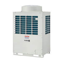
Carrier MMY-MAP1204FT9UL User Manual

Carrier MMY-MAP1204FT9UL
288 pages
To Next Page IconTo Next Page
Page #1 background imageLoading...
Page #1 background image
AIR CONDITIONER (MULTI TYPE)
SERVICE MANUAL
Outdoor Unit
< SUPER HEAT RECOVERY MULTI-i >
Model name:
MMY-MAP0724FT9UL
MMY-MAP0964FT9UL
MMY-MAP1204FT9UL
MMY-MAP0724FT6UL
MMY-MAP0964FT6UL
MMY-MAP1204FT6UL
Flow Selector Unit (FS unit)
Model name:
RBM-Y0383FUL
RBM-Y0613FUL
RBM-Y0963FUL
This service manual provides relevant explanations about new outdoor unit (SHRM-i).
Please refer to the following service manuals for each indoor units.
PRINTED IN JAPAN, Jun, 2013, TOMO
FILE No. A13-002
<4-Way Cassette Type> ........................
<Compact 4-Way Cassette Type> ........
<Ceiling Type> .......................................
<High Wall Type> ...................................
<Medium Static Ducted Type> ..................
<Slim Ducted Type> ..............................
<High Static Ducted Type> ...................
A10-019
A11-011
A11-020
Revision 1 : Jun., 2013
Revision 2 : Jul., 2013
Revision 3 : Dec., 2013
Revision 4 : Sep., 2014

Table of Contents

Questions and Answers:

Carrier MMY-MAP1204FT9UL Specifications

General IconGeneral
BrandCarrier
ModelMMY-MAP1204FT9UL
CategoryAir Conditioner
LanguageEnglish

Summary

Precautions for Safety

Specifications: 208/230V Model

Specifications: 208/230V Model (Continued)

Specifications: 460V Model

Specifications: 460V Model (Continued)

Wiring Diagram: Outdoor Unit

Wiring Diagram: Outdoor Unit (Continued)

Wiring Diagram: Outdoor Unit (MMY-MAP0964FT6UL, MMY-MAP1204FT6UL)

Wiring Diagram: Outdoor Unit (MMY-MAP0964FT9UL, MMY-MAP1204FT9UL)

Parts Rating: Outdoor Unit (208/230V)

Parts Rating: Outdoor Unit (460V)

Parts Rating: Outdoor Inverter (208/230V)

Parts Rating: Outdoor Inverter (460V)

Outdoor (Inverter) P.C. Board Layout

Interface P.C. board (MCC-1606)

Details the layout and connections of the Interface P.C. board (MCC-1606).

Inverter P.C. Board for Compressor (MCC-1595)

Inverter P.C. Board for Compressor (MCC-1596)

Inverter P.C. Board for Fan Motor (MCC-1610)

Noise Filter P.C. Board (MCC-1608 A, B)

Noise Filter P.C. Board (MCC-1625 A, B, C)

Refrigerant Piping Systematic Drawing

Model: MMY-MAP0724FTUL

Illustrates the systematic layout of the refrigerant piping for the MMY-MAP0724FTUL model.

Refrigerant Piping Systematic Drawing (Continued)

Model: MMY-MAP0964FTUL, MMY-MAP1204FTUL

Shows the refrigerant piping layout for MMY-MAP0964FTUL and MMY-MAP1204FTUL models.

System Refrigerant Piping Schematic Diagrams

Emergency Operation: Cooling Backup

Emergency Operation: Heating Backup

Refrigerant Recovery Procedure (Pump-Down)

Refrigerant Recovery Procedure (Pump-Down) (Continued)

Control Outline

PMV Control

Provides an overview of the system's control functions, including PMV operation.

A3-IPDU Control Functions

Applied Control with Optional Boards

Test Operation Procedure

Procedure and Summary of Test Operation

Outlines the step-by-step procedure for conducting a test operation.

Pre-Test Operation Checks

Check Items before Test Operation (before poweringon)

Lists essential items to check before powering on the system for test operation.

Pre-Test Operation Checks (With Central Control)

Checks After Main Power-on

Address Setup Procedures

Detailed Address Setup Procedure

Address Setup: Multi-Line Systems

Address Setup Procedure (Continued)

Post-Address Setup Checks (Central Control)

Troubleshooting During Test Operation

Check Codes Displayed on Remote Controller

Lists check codes displayed on the remote controller and their causes.

Troubleshooting: Remote Controller and Communication Issues

Test Operation Checks

Fan Check

Details how to perform fan checks as part of the test operation.

Test Operation: Cooling/Heating Check

Test Operation: Cooling/Heating Check (Continued)

Test Operation Criteria

Confirmation of Test Operation

Error Clearing Procedures

Error Clearing Procedures (Continued)

Pulse Motor Valve (PMV) Forced Operation

Solenoid Valve Forced Open/Close Function

Outdoor Unit Fan Operation Check

Troubleshooting Overview

Before engaging in troubleshooting

Provides an introduction to troubleshooting, applicable models, required tools, and normal behaviors.

Troubleshooting Method and Check Codes (Indoor Unit)

Check Codes: Remote Controller and Central Control

Check Codes: Outdoor Unit (Interface)

Check Codes: Outdoor Unit (Interface) (Continued)

Troubleshooting via Remote Controller Display

Checking and testing

Guides troubleshooting based on information displayed on the remote controller, including error history.

Troubleshooting Check Codes: Sensor and System Errors

Check Codes: Remote Controller and Outdoor Unit I/F Board

Check Codes: Remote Controller and Outdoor Unit I/F Board (Continued)

Check Codes: Outdoor Unit (IPDU and Communication Errors)

Check Codes: Sensor and System Errors (Outdoor)

Check Codes: Compressor and Oil Level Errors

Check Codes: Oil Level and TD Sensor Errors

Check Codes: TK Sensor and TD3 Sensor Errors

Check Codes: Indoor Unit and Address Errors

Check Codes: IPDU and Pressure Errors

Check Codes: Phase Errors, Fan, and Overflow

Check Codes: Gas Leak and Discharge Temperature Errors

Check Codes: TD3 Sensor and 4-Way Valve Errors

Check Codes: High-Pressure Protection and Fan IPDU Errors

Check Codes: TCC-LINK Central Control Device Errors

Diagnosis Procedures for Check Codes

Diagnosis Procedures for Check Codes (Continued)

7-Segment Display Functionality

Checking Procedure to Be Followed in Event of Abnormal Shutdown

Explains the use of the 7-segment display for checking operational status and abnormal shutdowns.

Oil Level Judgment Display

Interface P.C. Board: Switch and Function Settings

Leakage/Clogging Diagnosis: Refrigerant and Oil Circuits

Leakage/Clogging Diagnosis: Check Codes (MMY-MAP0964FT, 1204FT)

Troubleshooting: Flow Selector Unit (FS Unit)

Troubleshooting: Flow Selector Unit (FS Unit) (Continued)

Troubleshooting: Multiple Indoor Units with Cool/Heat FS Unit

Sensor Characteristics: Outdoor Unit Temperature Sensors

Pressure Sensor Characteristics (Outdoor Unit)

Sensor Characteristics: Indoor Unit Temperature Sensors

Pressure Sensor Output Check: Outdoor Unit (Pd Sensor)

Pressure Sensor Characteristics: Outdoor Unit (Ps Sensor)

Backup Operation (Emergency Operation)

Compressor Backup Operation Setting

Outdoor Unit Backup Setup Procedure

Outdoor Unit Refrigerant Recovery Method

Refrigerant Recovery from Failed Outdoor Unit (Pump-Down)

Covers methods for recovering refrigerant from failed outdoor units using pump-down.

Replacing Compressors

Compressor Replacement Procedure (Outline)

Gives a general overview of the steps involved in replacing a compressor.

Compressor Replacement: Oil Adjustment

Compressor Replacement: Oil Adjustment (Continued)

Troubleshooting Compressor Oil Shortage

Troubleshooting Compressor Oil Shortage (Continued)

Outdoor Unit Parts Replacement: Fan Motor

Outdoor Unit Parts Replacement: Fan Motor (Continued)

Outdoor Unit Parts Replacement: Heat Exchanger

Outdoor Unit Parts Replacement: Inverter Assembly

Outdoor Unit Parts Replacement: Inverter Assembly (Continued)

Replacing Circuit Boards/Components (Inverter Assembly - 208/230V)

Replacing Circuit Boards/Components (Inverter Assembly - 460V)

4-Way Valve: Detachment/Attachment (072 Type)

4-Way Valve: Detachment/Attachment (096/120 Type)

Outdoor Unit Parts Replacement: Transformer (460V)

Outdoor Unit Parts Replacement: Transformer (460V) (Continued)

P.C. Board Exchange Procedures

List of Service P.C. Boards

Provides a list of available service P.C. boards with their part numbers and applicable models.

Interface Board Replacement Procedure

Compressor IPDU P.C. Board (MCC-1595) Replacement

Compressor IPDU P.C. Board Replacement (Continued)

Fan IPDU P.C. Board (MCC-1610) Replacement Procedure

Fan IPDU P.C. Board Replacement (Continued)

Fan IPDU P.C. Board Replacement (MCC-1610) (Continued)

Noise Filter P.C. Board (MCC-1608 A, B) Replacement

Noise Filter P.C. Board Replacement (Continued)

Noise Filter P.C. Board (MCC-1625 A, B, C) Replacement

Exploded Diagram and Parts List: Outdoor Unit (MMY-MAP0724FT9UL)

Exploded Diagram and Parts List (MMY-MAP0724FT9UL) (Continued)

Refrigeration Circuit Diagram (MMY-MAP0724FT9UL)

Exploded Diagram and Parts List: MMY-MAP0964FT9UL / MMY-MAP1204FT9UL

Exploded Diagram and Parts List (MMY-MAP0964FT9UL / MMY-MAP1204FT9UL) (Continued)

Refrigeration Circuit Diagram (MMY-MAP0964FT9UL / MMY-MAP1204FT9UL)

Exploded Diagram and Parts List: MMY-MAP0724FT6UL

Exploded Diagram and Parts List (MMY-MAP0724FT6UL) (Continued)

Refrigeration Circuit Diagram (MMY-MAP0724FT6UL)

Exploded Diagram and Parts List: MMY-MAP0964FT6UL / MMY-MAP1204FT6UL

Exploded Diagram and Parts List (MMY-MAP0964FT6UL / MMY-MAP1204FT6UL) (Continued)

Refrigeration Circuit Diagram (MMY-MAP0964FT6UL / MMY-MAP1204FT6UL)

Exploded Diagram and Parts List: Flow Selector Unit (RBM-Y0383FUL, RBM-Y0613FUL)

Exploded Diagram and Parts List: Flow Selector Unit (RBM-Y0963FUL)

Warnings on Refrigerant Leakage

Check of Concentration Limit

Provides critical warnings about refrigerant leakage and concentration limits in rooms.

Related product manuals