Specifications are subject to change without notice.
17441 01 3400 02
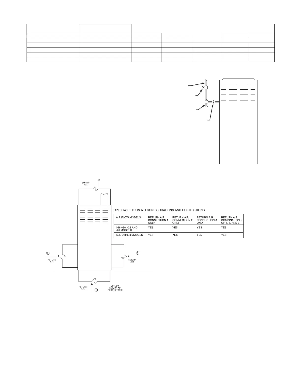
Table 6 – Maximum Capacity of Pipe*
NOMINAL IRON
PIPE
INTERNAL
DIAMETER
LENGTH OF PIPE --- FT. (M)
SIZE IN. (mm) In. ( mm) 10 20 30 40 50
1/2 (13) 0.622 (16) 175 (53) 120 (37) 97 (30) 82 (25) 73 (22)
3/4 (19) 0.824 (21) 360 (110) 250 (76) 200 (61) 170 (52) 151 (46)
1 (25) 1.049 (27) 680 (207) 465 (142) 375 (114) 320 ( 98) 285 (87)
1---1/4 (32) 1.380 (35) 1400 (427) 950 (290) 770 (235) 660 (201) 580 ( 177)
1---1/2 (38) 1.610 (41) 2100 (640) 1460 (445) 1180 (360) 990 ( 301) 900 (274)
* Cubic ft. of natural gas per hr for gas pressures of 0.5 psig (14 ---In. W.C.) or less and a pressure drop of 0.5 ---In. W.C. (based on a 0.60 specific gravity
gas). Ref: Chapter 6 current edition of ANSI Z223/NFPA 54.
Piping should be pressure and leak tested in accordance with
NFGC in the United States, local, and national plumbing and gas
codes before the furnace has been connected. After all
connections have been made, purge lines and check for leakage at
furnace prior to operating furnace.
If pressure exceeds 0.5 psig (14--In. W.C.), gas supply pipe must
be disconnected from furnace and capped before and during
supply pipe pressure test. If test pressure is equal to or less than
0.5 psig (14 -- In. W.C.), turn off electric shutoff switch located on
furnace gas control valve and accessible manual equipment
shutoff valve before and during supply pipe pressure test. After
all connections have been made, purge lines and check for
leakage at furnace prior to operating furnace.
The gas supply pressure shall be within the maximum and
minimum inlet supply pressures marked on the rating plate with
the furnace burners ON and OFF.
UNION
SEDIMENT
TRAP
MANUAL
SHUTOFF
VALVE
(REQUIRED)
GAS
SUPPLY
A02035
Fig. 18 -- T ypical Gas Pipe Arrangement
A02075
Fig. 19 -- Upflow Return Air Configurations and Restrictions
 Loading...