18
Fig. 16 — Typical Thermostat Wiring Connections
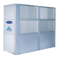
Step 7 — Install Plenums (if required)
The installation of 50XCA plenums is applicable to all vertical
discharge 50XCA units.
The following tools are required:
•
5
/
16
-in. nut driver
• adequate lifting device
• utility knife
• safety glasses
• work gloves
Install as follows:
1. Apply
3
/
4
-in. wide by
1
/
4
-in. thick gasket tape supplied with
unit to the bottom of mounting angles located on all four sides
of the plenum. Ensure edge of gasket is even with inside edge
of plenum walls and that there are no gaps in between insula-
tion strips. See Fig. 17.
2. Using appropriate lifting device, lift plenum and place on top
of 50XCA unit. Center plenum across both the width and
depth directions.
3. Using a
5
/
16
-in. nut driver, secure plenum mounting angles to
50XCA unit using 3 no. 10
5
/
8
-in. long screws provided with
plenum. Install 3 screws along each plenum side and 5 screws
along plenum front and rear mounting angles.
4. Adjust four-way deflection vanes as needed to ensure ade-
quate airflow distribution.
Fig. 17 — 50XC Plenum Unit
NOTE: Remote sensor is field-installed option.
W1
Y1
G
W3
CK1
CK2
R
C
W2
Y2
RS2
RS+5
RS1
RS GND
UNIT
GROUND
33CS250-01
R
G
Y1
C
Y2
TB2
50XC
(12 SIZE UNIT AND LARGER)
WIRE NUT
SHIELD (CUT AND
TAPE BACK)
REMOTE
ROOM
SENSOR
(P/N ZONECCORRS01)
W1
W2
D1
D2
IMPORTANT: Lockout and tagout all power supplies to
equipment and controls prior to servicing unit. Follow all safe-
ty codes, including working at safe heights.
MODEL
UNIT
SIZE
A B C D E
WGT
(lb)
50XCA900-200A00 06 51.3 14.0 26.8 30.0 10.0 65
50XCA900-201A00 08 51.3 14.0 26.8 45.0 10.0 65
50XCA900-202A00 12 66.0 14.0 28.9 60.0 10.0 80
50XCA900-203A00 14 66.0 19.0 28.9 48.0 15.0 80
50XCA900-204A00 16 86.0 19.0 28.9 60.0 15.0 115
50XCA900-205A00 24 86.0 19.0 28.9 80.0 15.0 115
NOTE: Dimensions are in inches.
 Loading...