Specifications subject to change without notice.
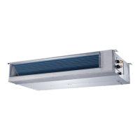
Fig. 1 — Sizes 09K - 48K
NOTE:
The 09K-48K unit can be mounted vertically as well as
horizontally.
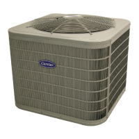
Fig. 2 — Size 58K
NOTES: Read the entire instruction manual before starting the
installation.
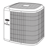
Images are for illustration purposes only. Actual models may
differ slightly.
TABLE OF CONTENTS
SAFETY CONSIDERATIONS.....................................................................2
INTRODUCTION.........................................................................................3
INSTALLATION REQUIREMENTS.............................................................4
DIMENSIONS..............................................................................................5
INSTALLATION CLEARANCES HORIZONTAL INSTALLATIONS ............7
MAINTENANCE CLEARANCES.................................................................7
INSTALLATION...........................................................................................8
Step 1 - Check Equipment ..........................................................................8
Step 2 - Mount Unit .....................................................................................8
Step 3 - Installing Ductwork.........................................................................10
Step 4 - Condensate Drain Installation........................................................11
Step 5 - Electrical Connections ...................................................................14
WIRING.......................................................................................................15
ELECTRICAL DATA....................................................................................16
CONNECTION DIAGRAMS ........................................................................16
Step 6 - Refrigerant Piping ..........................................................................17
WIRELESS REMOTE CONTROLLER INSTALLATION .............................18
WIRED REMOTE CONTROLLER INSTALLATION....................................18
START−UP .................................................................................................18
Step 7 - Setting Static Pressure or Automatic Airflow .................................19
FAN PERFORMANCES AT VARYING STATIC PRESSURES ..................20
SYSTEM CHECKS......................................................................................28
TROUBLESHOOTING ................................................................................29
ADVANCED SERVICE AND INSTALLATION FUNCTIONS ......................30
Installation Instructions
40MBDQ Ducted Slim Ductless System
Sizes 09 to 58