PG80VTLB: Installation, Start-up, Operating and Service and Maintenance Instructions
Manufacturer reserves the right to change, at any time, specifications and designs without notice and without obligations.
18
2. Route listed power cord through 7/8-in. (22 mm) diameter hole in
J-Box.
3. Secure power cord to J-Box bracket with a strain relief bushing or a
connector approved for the type of cord used.
4. Secure field ground wire to green ground screw on J-Box bracket.
5. Connect line voltage leads. (See Fig. 24).
6. Reinstall cover to J-Box. Do not pinch wires between cover and
bracket.
BX Cable Installation in Furnace J-Box
1. Remove cover from J-Box.
2. Route BX cable into 7/8-in. (22 mm) diameter hole in J-Box.
3. Secure BX cable to J-Box bracket with connectors approved for the
type of cable used.
4. Secure field ground wire to green ground screw on J-Box bracket.
5. Connect line voltage leads. (See Fig. 24).
6. Reinstall cover to J-Box. Do not pinch wires between cover and
bracket.
24-V Wiring
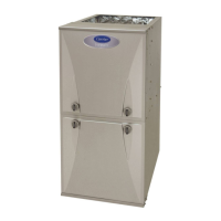
Make field 24-V connections at the 24-V terminal strip. (See Fig. 24 -
Fig. 29). Connect terminal Y/Y2 as shown in Fig. 30 for proper cooling
operation. Use only AWG No. 18, color-coded, copper thermostat wire.
The 24-V circuit contains an automotive-type, 3-amp. fuse located on
the control. Any direct shorts during installation, service, or maintenance
could cause this fuse to blow. If fuse replacement is required, use ONLY
a 3-amp. fuse of identical size.
ACCESSORIES
1. Electronic Air Cleaner (EAC)
Connect an accessory Electronic Air Cleaner (if used) using 1/4-in
female quick connect terminals to the two (2) male 1/4-in
quick-connect terminals on the control board marked EAC-1 and
EAC-2. The terminals are rated for 115 VAC, 1.0 amps maximum
and are energized during blower motor operation. (See Fig. 29).
2. Humidifier (HUM)
Connect an accessory 24 VAC, 0.5 amp. maximum humidifier (if
used) to the 1/4-in male quick-connect HUM terminal and
COM-24V screw terminal on the control board thermostat strip.
The HUM terminal is energized when the inducer motor is
energized in heating. (See Fig. 29).
NOTE: For 24V & 115V EAC or Humidifier Accessory details, see
Accessory instructions.
Thermostats
A single stage heating and cooling thermostat can be used with the
furnace. The furnace control board CPU will control the furnace and
outdoor unit staging. A two stage heating and cooling thermostat can
also be used to control the staging. For two stage thermostat control of
the furnace staging, on the 3 digit display, navigate to Htt and select
(2St). For two stage thermostat control of a 2-stage outdoor unit,
navigate to Ctt and select (2St). Refer to typical thermostat wiring
diagrams and the Sequence of Operation section for additional details.
Consult the thermostat installation instructions for specific information
about configuring the thermostat.
A11157
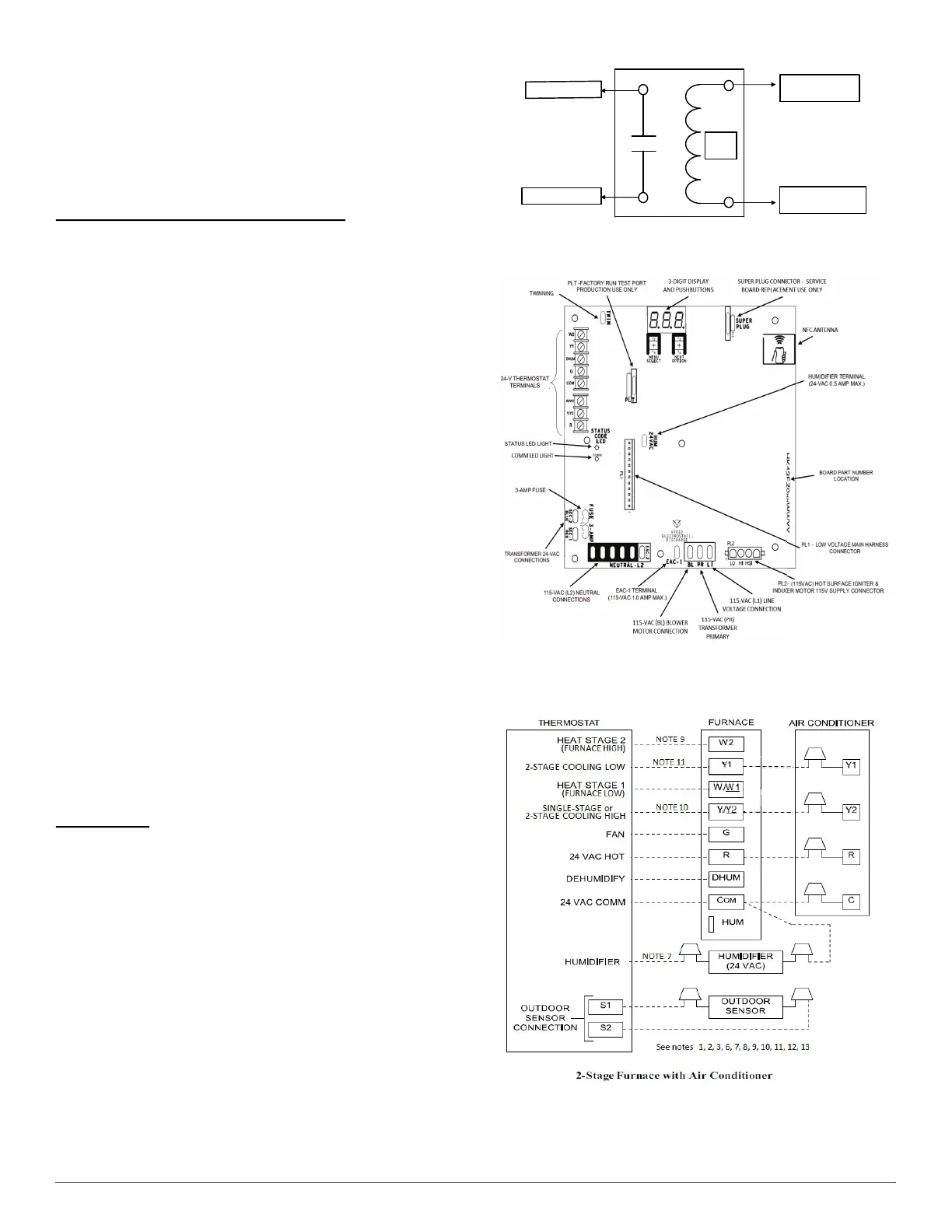
Fig. 28 – Field-supplied Isolation Relay for Humidifiers with
Internal Power Supply
A221518
Fig. 29 – Example of Variable Speed Furnace Control for ECM
Blower Motor
A230176
24 V
Coil
To Humidifier Leads
To Com/24V Screw Terminal
on Thermostat Strip
To HUM Terminal On
Furnace Control Board
To Humidifier Leads



 To Next Page