PG80VTLB: Installation, Start-up, Operating and Service and Maintenance Instructions
Manufacturer reserves the right to change, at any time, specifications and designs without notice and without obligations.
19
A230177
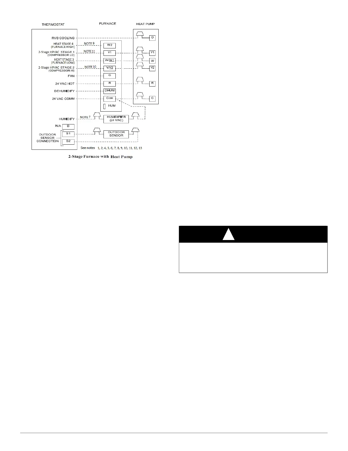
Fig. 30 – Thermostat Connection for Two-Stage Furnace and A/C &
Heat Pump
Notes for thermostat drawings:
1. Thermostat output signals may vary. Consult thermostat installation
instructions for more information.
2. Refer to outdoor equipment Installation Instructions for additional
information and setup procedure.
3. Configure the thermostat for air conditioner installations. Refer to
thermostat instructions.
4. Configure thermostat for dual fuel operation. Refer to thermostat
instructions.
5. Heat pump MUST have a high pressure switch for dual fuel
applications.
6. For Single-stage AC or HP, configure thermostat for single-stage
compressor operation. Refer to thermostat instructions.
7. NO connection should be made to the furnace HUM terminal when
using a thermostat with a 24 volt humidifier output.
8. For Two-Stage AC or HP, thermostat may be configured for
two-stage compressor operation, allowing the thermostat to control
staging, or thermostat may be configured for single stage operation,
allowing furnace control to control staging. Refer to note 10 and
thermostat instructions.
9. Optional connection - See Sequence of Operations, Heating
adaptive mode for additional information. If two-stage heating
thermostat output is connected to W/W1 and W2 on Modulating or
Two-stage furnace control, Heating Thermostat Type (Htt) setting
on furnace control should be set to “2St” to allow thermostat to
control furnace staging.
10. For Two-stage outdoor equipment, connection is Optional - See
Cooling sequence of operations (adaptive mode) for additional
information. If two-stage HP/cooling thermostat is connected to Y1
and Y/Y2 on Modulating or Two-stage furnace control board,
Cooling Thermostat Type (Ctt) (setting on furnace control) should
be set to “2St” to allow thermostat to control outdoor unit staging.
11. For Single-stage outdoor equipment, connect thermostat HP or AC
output to Y/Y2 of furnace control.
12. Configure Dehumidify function to remove 24 VAC from Dehum
terminal on a demand to dehumidify. Consult thermostat
installation instructions for more information.
13. Thermostat terminal connection order on furnace control may vary-
reference furnace control labeling for designations.
VENTING
The furnace shall be connected to a listed factory built chimney or vent,
or a clay-tile lined masonry or concrete chimney. Venting into an unlined
masonry chimney or concrete chimney is prohibited.
When an existing Category I furnace is removed or replaced, the original
venting system, may no longer be sized to properly vent the attached
appliances. An improperly sized Category I venting system could cause
the formation of condensate in the furnace and vent, leakage of
condensate and combustion products, and spillage of combustion
products into the living space.
Vent system or vent connectors may need to be resized. Vent systems or
vent connectors must be sized to approach minimum size as determined
using appropriate table found in the current edition of NFPA 54/ANSI
Z223.
General Venting Requirements
Follow all safety codes for proper vent sizing and installation
requirements, including local building codes, the National Fuel Gas
Code NFPA 54/ANSI Z223.1, Parts 12 and 13 in the United States, the
local building codes, and furnace and vent manufacturers’ instructions.
These furnaces are design-certified as Category I furnaces in accordance
with ANSI Z21.47/CSA 2.3 and operate with a non-positive vent static
pressure to minimize the potential for vent gas leakage. Category I
furnaces operate with a flue loss not less than 17% to minimize the
potential for condensation in the venting system. These furnaces are
approved for common venting and multi-story venting with other fan
assisted or draft hood equipped appliances in accordance with the
NFCG, local building codes, and furnace and vent manufacturers’
instructions.The following information and warning must be considered
in addition to the requirements defined in the NFPA 54/ANSI Z223.
1. If a vent (common or dedicated) becomes blocked, the furnace will
be shut off by the draft safeguard switch located on the vent elbow.
2. Two-stage furnaces require Type B vent connectors outside the
casing in all configurations. Single wall vent connector may be
used inside the furnace casing with the transition to Type B vent
outside the furnace casing. Size the connector so that the FAN-Min
vent connector capacity is equal to or lower than the low fire rate of
the furnace and the FAN-Max vent connector capacity is equal to or
higher than the furnace high fire rate.
3. Do not vent this Category I furnace into a single wall dedicated or
common vent. The dedicated or common vent is considered to be
the vertical portion of the vent system that terminates outdoors.
4. Vent connectors serving Category I furnaces shall not be connected
into any portion of a mechanical draft system operating under
positive pressure.
5. Do not vent this appliance with any solid fuel burning appliance.
6. Category I furnaces must be vented vertically or nearly vertically
unless equipped with a listed mechanical venter. See SIDEWALL
VENTING section.
7. Do not vent this appliance into an unlined masonry chimney. (Refer
to Chimney Inspection Chart, Fig. 31).
WARNING
!
CARBON MONOXIDE POISONING HAZARD
Failure to follow this warning could result in personal injury or death.
Do not bypass the draft safeguard switch, as an unsafe condition could
exist which must be corrected.



 To Next Page