51
Marine option, dry contact, NO,
connected on terminals to ICCP
Marine option, dry contact
User option / not connected in std
User option / not connected in std
Table 13 – PIC 5 – 19DV I/Os mapping list
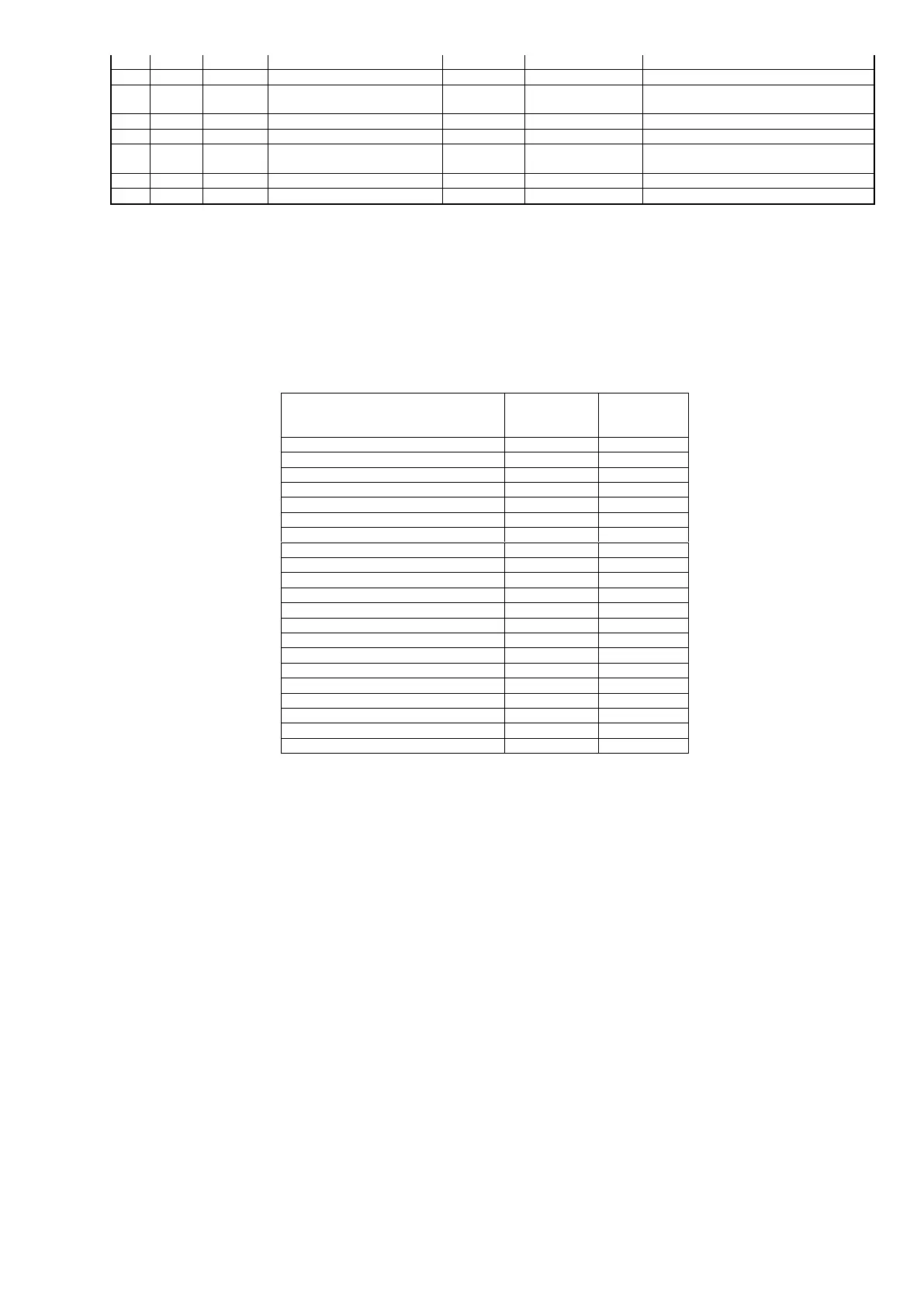
Terminal
identification -
TB5
Power supply 24AC for Digital Output
* : chiller status in standard, %capacity load in option.
Table 14 – PIC 5 – 19DV I/Os terminal identification