– 99 –
U3 U4
U1 U2 U5 U6
U1 U2
A B
U3 U4
U1 U2 U5 U6
U1 U2
A B
U3 U4
U1 U2 U5 U6
U1 U2
A B
U3 U4
U1 U2 U5 U6
U1 U2
A B
U3 U4
U1 U2
U1
U3
U2
U4
U5 U6
U1 U2
A B
Central remote
controller
Header
unit
Follower unit
Follower unit
Remote
controller
Remote
controller
Remote
controller
Remote
controller
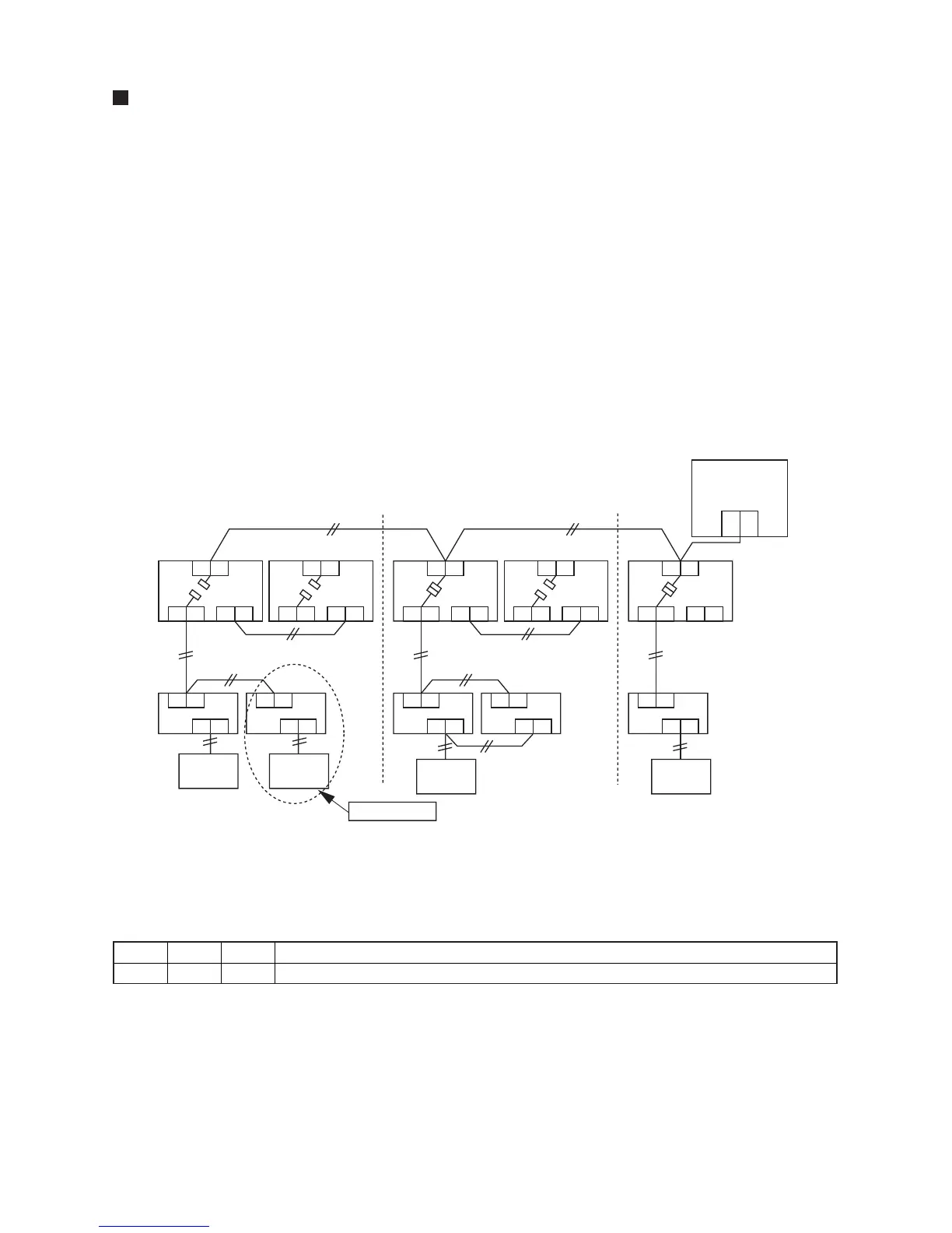
Added indoor unit
Header
unit
Header
unit
In the case of an increase in address-undefined indoor units
(extension, etc.)
To set up the indoor address of a unit with an address that is undefined due to the extension of indoor units or
replacement of PC board, etc., follow the methods below.
Method 1
Set up an address individually from a wired remote controller.
(Line address, Indoor address, Group address, Central address)
For the setup method, refer to “Manual address setup from the remote controller.” above.
Method 2
Set up an address from the outdoor unit.
* Leave the addresses of the units for which addresses have already been set up as they are. Set up an
address only for the unit where the address is undefined.
Addresses are allocated from lower numbers.
Setup procedure
Set up the outdoor header units in the refrigerant line to which indoor units have been added, as follows.
1 Remove the relay connector between U1/U2 and U3/U4.
2 If it is off, turn on SW30-bit 2 on the interface PC board at outdoor header unit side.
* Turn off the power, and then execute the operation.
3 Turn on the indoor/outdoor power for the refrigerant line for which an address is to be set
up.
After approximately 1 minute, check that “U.1. - - -” is displayed on the 7-segment display.
4 Execute the following operation on the interface PC board of the header unit.
“AUTO1” → “AUTO2” → “AUTO3” → ... → “AUTO9” ... is counted and displayed on the 7-segment display.
5 When “U.1. - - -” is displayed on the 7-segment display, the setup operation finished.
Turn off the indoor/outdoor power.
6 Return to the following setup as before.
• Relay connector
• SW30-bit 2
• SW01, SW02, SW03
SW01 SW02 SW03 SW04
2 14 2 After checking that “In.At” is displayed on the 7-segment display, push SW04 for 5 seconds or more.
 Loading...