10
NOTE: The W7220 will be in the ”set up” mode for the
first 60 minutes after powered. If a sensor for OA air or
bus device (sensor, actuator) is disconnected during the set
up mode, the W7220 will not alarm that failure. The MA
sensor is a system ”critical”sensor, if the MA sensor is
removed during the set up mode, the W7220 will alarm.
After 60 minutes the W7220 controller will change to
operation mode and all components removed or failed will
alarm in the operation mode.
INSTALLATION AND SETUP
The following installation procedures should be
performed in the order listed:
1. Mounting — see Fig. 5 (on page 9).
2. Wiring — see pages 4, 5 and 6.
3. Interface and Programming overview – see page 11.
4. Setup and Configuration — see page 12
5. Checkout — see page 23.
Troubleshooting and Alarms—see page 24.
Economizer Module Wiring Details
The wiring connection terminals for each module/sensor are:
S “W7220 Economizer Module Wiring” on pages 10 -- 11.
S “S--Bus Sensor Wiring” on page 11
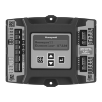
W7220 Economizer Module Wiring
Use Fig. 6 and Tables 1 and 2 to locate the wiring
terminals for the Economizer module.
NOTE: The four terminal blocks are removable. You can
slide out each terminal block, wire it, and then slide it
back into place.
W7220 Controller
Left Terminal
Block Label
Right Terminal
Block Label
NOTE: The bottom 4 Pin actuator header is not used
C14156
Fig. 6 -- W7220 Economizer Module Terminal
Connection Labels.
Table 1 – Economizer Module --
Left Hand Terminal Blocks
Label Type Description
Top Left Terminal Block
MAT
MAT
20k NTC
and
COM
Supply Air Temperature Sensor
(polarity insensitive connection)
OAT
OAT
20k NTC
and
COM
Outdoor Air Temperature Sensor
(polarity insensitive connection)
S --- B U S
S --- B U S
S --- B u s
(Sylk Bus)
Enthalpy Control Sensor
(polarity insensitive connection)
Bottom Left Terminal Block
I A Q 2 --- 1 0 2 --- 1 0 V d c Air Quality Sensor Input
(e.g. CO
2
sensor)
IAQ COM COM Air Quality Sensor C ommon
IAQ 24V 24 V ac Air Quality Sensor 24 Vac Source
A C T 2 --- 1 0 2 --- 1 0 V d c Damper Actuator Output (2---10 Vdc)
ACT COM COM Damper Actuator Output Common
ACT 24V 24 V ac Damper Actuator 24 Vac Source
n/a The bottom pin is not used.
Table 2 – Economizer Module --
Right Hand Terminal Blocks
Label Type Description
Top Ri g h t Te r min a l Bl ock
n/a The first pin is not used
AUX2 I 24 V ac IN Shut Down (SD) or Heat (W)
Conventional only
or
Heat Pump Ch angeover (O/B) in
Heat Pump mode.
OCC 24 V ac IN Occupied / Unoccupied Input
E --- G N D E --- G N D Earth Ground --- System Required
EXH1 24 V ac OUT Exhaust Fan 1 Output
AUX1 O 24 Vac OUT Programmable:
Exhaust fan 2 output
or
Erv
or
System Alarm output
Bottom Right Terminal Block
Y 2 --- I 24 Vac IN Y2 in --- Cooling Stage 2 Input from
space thermostat
Y 2 --- O 24 V ac OUT Y2 out --- Cooling Stage 2 Output to
stage 2 mechanical cooling
Y 1 --- I 24 Vac IN Y1 in --- Cooling Stage 1 Input from
space thermostat
Y 1 --- O 24 V ac OUT Y1 out --- Cooling Stage 1 Output to
stage 1 mechanical cooling
C COM 24 Vac Common
R 24 V ac 24 V ac Power (Hot)
SUP--TI24--02SI
 Loading...