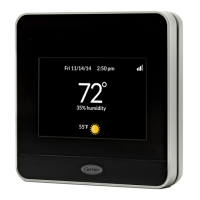
Do you have a question about the Carrier TC-PHP01-BLK and is the answer not in the manual?
Configures thermostat for system types: HP, H2, AC, A2, H, C.
Selects temperature units: Fahrenheit (F) or Centigrade (C).
Determines fan operation with heat; useful for systems with separate blower control.
Controls thermostat timers for zoned or non-zoned HVAC systems.
Configures heat pump reversing valve operation for cooling or heating.
Sets minimum temperature difference between heating and cooling setpoints.
Manages temperature transitions for energy efficiency and comfort based on schedule.
Calibrates displayed temperature by adding or subtracting degrees.
Allows automatic switching between heating and cooling modes.
Limits heating/cooling cycles per hour for equipment protection.
Sets minimum time between heat pump stages to manage auxiliary heat usage.
Controls display backlight behavior: always on or on demand.
Enables/disables keypad lockout to prevent unintended changes.
Switches between programmable/non-programmable modes, disabling scheduling.
Defines daily programmable periods (2 or 4) for temperature scheduling.
Sets the lowest allowable temperature for cooling mode.
Sets the highest allowable temperature for heating mode.
Resets all thermostat settings, programs, clock, and day to factory defaults.
Illustrates typical wiring for a single-speed AC system.
Shows typical wiring for a single-speed heat pump system.
Details wiring for single-stage furnace with AC and split power.
Wiring diagram for multi-stage furnace and 2-stage AC systems.
Wiring for multi-stage furnace and 2-stage heat pump systems.
Wiring diagram for FV/FK fan coil with 2-stage air conditioner.
Wiring diagram for FV/FK fan coil with 2-stage heat pump.
Steps to diagnose and resolve issues when the thermostat fails to power on.
Troubleshooting steps for when the thermostat's backlight does not illuminate.
Explains common error codes and implications, often requiring replacement.
| Brand | Carrier |
|---|---|
| Model | TC-PHP01-BLK |
| Category | Thermostat |
| Language | English |
