INSTALLATION
Step 1 -- Thermostat Location
Thermostat should be mounted:
• Approximately 5 fl (1.5 m) from floor.
• Close to or in a frequently used room, preferably on an
inside partitioning wall.
• On a section of wall without pipes or ductwork.
Thermostat should NOT be mounted:
• Close to a window, on an outside wall, or next to a door
leading to the outside.
• Exposed to direct light and heat from a lamp, sun, fire-
place, or other temperature-radiating object which may
cause a false reading.
• Close to or in direct airflow from supply registers and
return-air grilles.
In areas with poor air circulation, such as behind a door or
in an alcove.
Step 2 -- Select Model
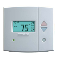
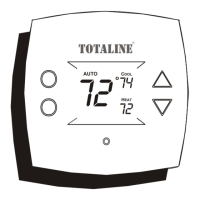
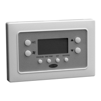
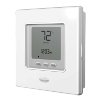
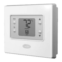
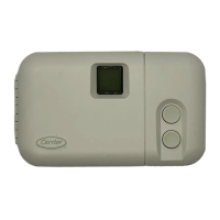
P274-0100-C (l-stage cool, l-stage heat) is to be used for
single-stage heating and/or cooling applications only. It
CANNOT be used with optional outdoor temperature sensol:
(See Table 1.)
P274-0200-C (l-stage cool, 2-stage heat) can be used with a
single-speed heat pump (HP), or tin air conditioner (AC) with a
2-stage furnace or fan coil. When using the thermostat
softwme (Configuration mode) select Option 5, HP/AC con-
figuration. This thermostat comes configured from the factory
as a heat pump thermostat. Select AC in Option 5 for AC oper-
ation. When AC operation is selected, the O/W2 terminal is
converted from a reversing valve output (O) to a second-stage
heat output (W2). This output can be used to control 2-stage
furnaces or 2-stage electric heat in fan coils. (See Table 1.)
P274-0300-C is for 2-speed compressor systems only (HP and
AC). Output YI controls compressor low speed and output
Y/Y2 controls compressor high speed. (See Table 1.)
Step 3 -- Install Thermostat
c. As each wire is disconnected, record wire color
and terminal marking.
d. Discard or recycle old thermostat.
NOTE: Mercury is a hazardous waste and MUST be dis-
posed of properly.
3. Open thermostat (mounting base) to expose mounting
holes. The base can be removed to simplify mounting.
Snap apart carefully to separate mounting base from
remainder of thermostat.
NOTE: If thermostat will not separate, insert a small screw-
driver into top slots for ease of separation.
4. Route thermostat wires through large hole in mounting
base. Level mounting base against wall (for aesthetic
value only -- thermostat need not be leveled for
proper operation) and mark wall through 2 mounting
holes.
5. Drill two 3/lr,-in. mounting holes in wall where
marked.
6. Secure mounting base to wall with 2 anchors and
screws provided, (additional anchoring holes available
for more secure mounting if needed) making sure all
wires extend through hole in mounting base.
7. Adjust length and routing of each wire to reach proper
terminal and connector block on mounting base with
I/4 in. extra wire. Strip only 1/4 in. insulation from each
wire to prevent adjacent wires from shorting together
when connected.
8. Match and connect equipment wires to proper termi-
nals of the connector blocks. (See Table 1.)
ELECTRICAL OPERATION HAZARD
Failure to follow this caution may result in equipment dim-
age or improper operation.
hnproper winng or installation may dmnage the therlno-
stat. Check to make sure wiring is correct before proceed-
ing with installation or turning on unit.
ELECTRICAL SHOCK HAZARD
Failure to follow this wmning could result in personal
injury or death.
Before installing thermostat, turn off all power to unit.
There may be more than 1 power disconnect.
I.
2.
Turn OFF all power to unit.
If an existing thermostat is being replaced:
a. Remove existing thermostat from wall.
b. Disconnect wires from existing thermostat, one at
a time. Be careful not to allow wires to fall back
into the wall.
9. Push any excess wire into wall and against mounting
base. Seal hole in wall to prevent air leaks. Leaks can
affect operation.
10. Snap case back together.
11. Close thermostat assembly making sure pins on back
of circuit board align with sockets in connector.
12. Turn ON power to unit.
NOTE: If a common wire has not been connected two AA
batteries must be used to power the thermostat.
Table 1 -- Model Selection and Wiring Diagram Chart
AIR CONDITIONER HEAT PUMP
INDOOR UNIT
1 Speed 2 Speed 1 Speed 2 Speed
1-Stage Model 0100-C Model 0300-C Requires Requires
Heat See Fig. 2 See Fig. 8 Dual Fuel Thermostat Dual Fuel Thermostat
2-Stage Model 0100-C Model 0200-C Model 0300-C Requires Requires
Heat See Fig. 3 See Fig. 5 See Fig. 9 Dual Fuel Thermostat Dual Fuel Thermostat
Model 0100-C Model 0200-C Model 0300-C Model 0200-C Model 0300-C
Typical Fan Coil See Fig. 4 See Fig. 6 See Fig. 10 See Fig. 7 See Fig. 11
Variable-Speed Fan Coil Model 0100-C Model 0200-C Model 0300-C Model 0200-C Model 0300-C
(FK4D, FV4, 40FK) See Fig. 12 See Fig. 13 See Fig. 14 See Fig. 15 See Fig. 16
*Model 0100-C will only cycle through 1-stage heat, but can properly operate when installed on a 2-stage heat system.

 Loading...
