DEHUMIDIFYEQUIPMENTANDCONNECTIONS
Thedehumidifyoutputconnectstothedehumidifyinputon
variable-speedfurnacesand fan coils. Additional
dehumidificationisdonebycontrollingthecompressor.Avariety
ofoperatingmodesareavailable.
ELECTRICAL OPERATION HAZARD
Failure to follow this warning could result in personal
injury or death.
DO NOT connect furnace HUM terminal directly to
Thermidistat HUM terminal. This will bypass furnace
safety controls. See Low Voltage Wiring Diagrams and
notes for proper connection.
OUTDOOR TEMPERATURE SENSOR
Optimum performance is obtained when an outdoor temperature
sensor is used with the Thermidistat Control. Plan installation so
that 2 wires can be run from Thermidistat Control to an outdoor
location, preferably on the north side of the house or refer to
Installation Instructions included with the outdoor temperature
sensor for simplified connection. Sensor can be mounted to
outdoor unit and existing control wires may be used for its
connection. Details are provided in sensor instructions.
INSTALLATION
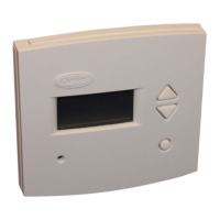
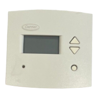
Step 1-- Thermidistat Control Location
• Approximately 5 ft (1.5m) from floor.
• Close to or in a frequently used room, preferably on an inside
partitioning wall.
• On a section of wall without pipes or duct work.
Thermidistat Control should NOT be mounted
• Close to a window, on an outside wall, or next to a door leading
to the outside.
• Exposed to direct light or heat from a lamp, sun, fireplace, or
other temperature-radiating objects which could cause a false
reading.
• Close to or in direct airflow from supply registers and return-air
registers.
• In areas with poor air circulation, such as behind a door or in an
alcove.
Step 2--Set DIP Switches
There is a 4 section DIP switch within tire Thermidistat Control
which must be properly set by the installer. It is easiest to set these
4 switches before the Thermidistat Control is mounted to the
wall, so STOP and complete the following steps.
1. Open hinged Thermidistat Control cover.
2. Remove cover completely by snapping it apart at hinge.
3. Open Thermidistat Control by pressing back half of the
right end of plastic case inward while, at the same time,
pulling front and back halves apart at the right end. The 2
halves will swing apart.
4. Snap hinge apart to completely separate the 2 halves.
5. Switches are located in upper right corner of circuit board.
To change switch position, use corner of a small
screwdriver to slide switch to opposite position.
6. After switches have been set. do not reassemble the 2
halves. The rear plastic will first be mounted to the wall.
SWITCH 1--AC/HP SELECT
Use this switch to select between air conditioner and heat pump
systems.
TO SET
OFF--for air conditioner installations. This is factory default.
ON--for heat pump installations, using either a fan coil or
furnace (Hybrid Heat).
SWITCH 2--1 SPEED/2 SPEED
This switch tells the system whether the compressor is 1 or 2
stage.
TO SET
OFF--for single-speed compressor. This is factory default.
ON--for 2-speed compressors, whether AC or HP.
SWITCH 3--SMART/CONVENTIONAL RECOVERY
Selects between conventional and smart recovery from setback.
Conventional recovery changes to new set point at programmed
time. Smart recovery, which is active in both heating and cooling,
starts 90 minutes earlier and smoothly adjusts set point so room
will arrive at programmed temperature at programmed time.
TO SET
OFF--for smart recovery. This is factory default.
ON--for conventional recovery.
SWITCH 4--INSTALLER TEST OFF/ON
Selects a special installer test mode which assists with system
startup and checkout. See Step 5, System Startup and Check-out.
TO SET
OFF--for normal operation. This is factory default.
ON--for installer test mode.
Step 3--Install Thermidistat Control
ELECTRICAL OPERATION HAZARD
Failure to follow this warning could result in personal
injury or death.
Before installing Thermidistat Control. turn off all power
to equipment. There may be more than 1 power
disconnect.
1. Turn off all power to equipment.
2. If an existing thermostat is being replaced
a. Remove existing thermostat from wall.
b. Disconnect wires from existing thermostat. 1 at a time.
c. As each wire is disconnected, record wire color and
terminal marking.
d. New or additional wire may be needed to accommodate
added humidity outputs.
e. Discard or recycle old thermostat.
NOTE: Mercury is a hazardous waste and MUST be disposed of
properly.
3. Hold the Thermidistat Control rear plastic. (If it is not
separated from the remainder of the Thermidistat _'_
Control, refer to Step 2 above.)
4. Route wires through large hole in rear plastic. Level rear
plastic against wall (for aesthetic value only--Thermidistat
Control need not be leveled for proper operation) and
mark wall through 2 mounting holes.
5. Drill two 3/16-in. mounting holes in wall where marked.
6. Secure rear plastic to wall with 2 screws and anchors
provided. Additional mounting holes are available for

 Loading...