EasyManua.ls Logo

Carrier TSTATCCN2S01-C - User Manual

Carrier TSTATCCN2S01-C
12 pages
Print Icon
To Next Page IconTo Next Page
Loading...
Non-Programmable Thermostat
TSTATCCN(AC,HP,2S)01-C
Installation and Operating Instructions
NOTE: Read the entire instruction manual before starting the
installation.
This symbol indicates a change since the last issue.
SAFETY CONSIDERATIONS
Read and follow manufacturer instructions carefully. Follow all
local electrical codes during installation. All wiring must conform
to local and national electrical codes. Improper wiring or installa-
tion may damage thermostat.
Recognize safety information. This is the safety-alert symbol
.
When you see this symbol on the equipment and in the instruction
manual, be alert to the potential for personal injury.
Understand the signal words DANGER, WARNING, and CAU-
TION. These words are used with the safety-alert symbol.
DANGER identifies the most serious hazards which will result
in severe personal injury or death. WARNING signifies a hazard
which could result in personal injury or death. CAUTION is used
to identify unsafe practices which would result in minor personal
injury or product and property damage. NOTE is used to highlight
suggestions which may result in enhanced installation, reliability,
or operation.
INTRODUCTION
Carrier thermostats are wall-mounted, low-voltage thermostats
which maintain room temperature by controlling the operation of
a heating and air conditioning system. Separate heating and
cooling setpoints, plus auto changeover provide maximum comfort
and flexibility. Batteries are optional; temperature and mode
settings are preserved with the power off.
INSTALLATION CONSIDERATIONS
Power
Note that all thermostats are dual powered where batteries can be
installed or in the presence of R and C (24vac) are not required. 2
AA batteries are furnished with the product.
Models
There are 3 different models. The 9th and 10th letters of the part
number indicate the model. These 2 letters also appear on the
package and on the circuit board. Be sure to have the proper
thermostat for the intended application. Models are:
AC 1-stage cool, 1-stage heat for AC systems only.
HP 1-stage cool, 2-stage heat for either HP, or AC with 2-stage
heat.
2S 2-stage cool, 2-stage heat for 2-speed AC systems, or
2-stage cool, 3-stage heat for 2-speed HP systems.
Use each only for its intended purpose. See Table 1.
INSTALLATION
Step 1—Thermostat Location
Thermostat should be mounted:
Approximately 5 ft. (1.5m) from floor.
Close to or in a frequently used room, preferably on an inside
partitioning wall.
On a section of wall without pipes or duct work.
Thermostat should NOT be mounted:
Close to a window, on an outside wall, or next to a door leading
to the outside.
Exposed to direct light and heat from a lamp, sun, fireplace, or
other temperature-radiating object which may cause a false
reading.
Close to or in direct airflow from supply registers and return-air
grilles.
In areas with poor air circulation, such as behind a door or in
an alcove.
Step 2—Select Model
AC Model (1-stage cool, 1-stage heat) is to be used for single-
stage heating and/or cooling applications only. It CANNOT be
used with optional outdoor temperature sensor. (See Table 1.)
HP Model (1-stage cool, 2-stage heat) can be used with a
single-speed heat pump (HP), or an air conditioner (AC) with a
2-stage furnace or fan coil. Software Option 5 selects HP/AC
operation. This thermostat comes configured from the factory as a
heat pump thermostat. Select AC in software Option 5 for AC
operation. When AC operation is selected, the O/W2 terminal is
converted from a reversing valve output (O) to a second-stage heat
output (W2). This output can be used to control 2-stage furnaces or
2-stage electric heat in fan coils. (See Table 1.)
2S Model is for 2-speed compressor systems only (HP and AC).
Output Y1 controls compressor low speed and output Y/Y2
controls compressor high speed. (See Table 1.)
HEIGHT (IN.) WIDTH (IN.) DEPTH (IN.)
3-1/2 5-3/4 1-3/8
Fig. 1—Carrier Non-Programmable Thermostat
TSTATCCNAC01-C
TSTATCCNHP01-C
TSTATCCN2S01-C
A04103
Visit www.carrier.com
Manufacturer reserves the right to discontinue, or change at any time, specifications or designs without notice and without incurring obligations.
Book
TabPC 101 Catalog No. 03TS-TA54 Printed in U.S.A. Form TSTAT-30SI Pg 1 08-04 Replaces: New
Question and Answer IconNeed help?

Do you have a question about the Carrier TSTATCCN2S01-C and is the answer not in the manual?

Summary

Safety Considerations

General Safety

Read and follow manufacturer instructions carefully. Follow all local electrical codes during installation.

Installation Steps

Step 1: Thermostat Location

Thermostat should be mounted: Approximately 5 ft. (1.5m) from floor. Close to or in a frequently used room, preferably on an inside partitioning wall.

Step 2: Select Model

AC Model (1-stage cool, 1-stage heat) is to be used for single-stage heating and/or cooling applications only.

Installation Safety Warnings

Electrical Shock Hazard

Failure to follow this warning could result in personal injury or death. Before installing thermostat, turn off all power to unit.

Electrical Operation Hazard

Failure to follow this caution may result in equipment damage or improper operation. Improper wiring or installation may damage the thermostat.

Thermostat Configuration Setup

Step 4: Set Thermostat Configuration

Configuration options are intended to be selected at installation and are normally not modified by the home owner.

Configuration Options - Part 1

Configuration Options - Part 2

Configuration Options & Installer Operations

Installer Test Mode

Installer test will be initiated by pressing the fan button for 20 seconds (15 seconds will enter installer setup).

Operational Information

Error Codes

If the thermostat cannot properly read room temperature, the display will indicate -- (2 dashes) and all outputs (except the fan if on) will turn off.

Thermostat Troubleshooting

Blank LCD Troubleshooting

Check for 24vac between R and C at terminal connections or battery. Temperature sensor reading out of range.

E2 Error Code Troubleshooting

Brownout condition or too low of voltage to thermostat. Double check wiring and check for 24vac between R and C.

E3 Error Code Troubleshooting

The outdoor temperature sensor is open, not connected, or shorted.

Cooling Not Operating Troubleshooting

Select COOL mode. Set desired temperature to 10°F below room temperature. Simulateously press FAN and INCREASE TEMPERATURE buttons to defeat timers.

Heating Not Operating Troubleshooting

Select HEAT mode. Set desired temperature to 10°F above room temperature. Simulateously press FAN and INCREASE TEMPERATURE buttons to defeat timers.

Overview

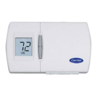
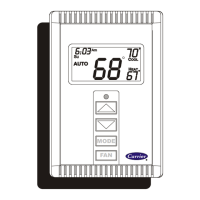
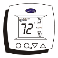
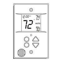
This document provides installation and operating instructions for Carrier Non-Programmable Thermostats, specifically models TSTATCCN(AC,HP,2S)01-C. These are wall-mounted, low-voltage thermostats designed to maintain room temperature by controlling heating and air conditioning systems.

Function Description

The thermostats offer separate heating and cooling setpoints, along with an auto changeover feature for maximum comfort and flexibility. They are dual-powered, capable of operating with 24VAC (R and C terminals) or two AA batteries (included). Temperature and mode settings are preserved even without power.

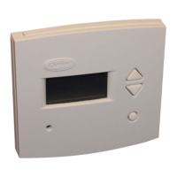
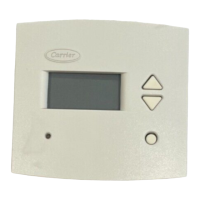
Three distinct models are covered:

  • AC Model (1-stage cool, 1-stage heat): Designed for single-stage heating and/or cooling applications only. It cannot be used with an optional outdoor temperature sensor.
  • HP Model (1-stage cool, 2-stage heat): Can be used with a single-speed heat pump (HP) or an air conditioner (AC) with a 2-stage furnace or fan coil. Software Option 5 allows selection between HP/AC operation. When AC operation is selected, the O/W2 terminal converts from a reversing valve output (O) to a second-stage heat output (W2), suitable for controlling 2-stage furnaces or 2-stage electric heat in fan coils.
  • 2S Model (2-stage cool, 2-stage heat): Exclusively for 2-speed compressor systems (HP and AC). Output Y1 controls compressor low speed, and Y/Y2 controls compressor high speed.

Important Technical Specifications

  • Power: Dual powered (24VAC or 2 AA batteries).
  • Dimensions: Height: 3-1/2 inches, Width: 5-3/4 inches, Depth: 1-3/8 inches.
  • Temperature Accuracy: Factory calibrated within an accuracy of plus or minus 1°F.
  • Cycle Rate: Limited to a maximum of 6 equipment cycles per hour, regardless of anticipator setting.
  • Timers:
    • Five-minute Compressor Timeguard: Prevents the compressor from starting unless it has been off for at least 5 minutes. Can be defeated for one cycle by simultaneously pressing the FAN mode button and the INCREASE TEMPERATURE button.
    • Fifteen-minute Cycle Timer: Prevents a new heating or cooling cycle from starting until at least 15 minutes after the last start of the same cycle, ensuring equipment is not cycled more than 4 times per hour. Can be defeated for one cycle by manually changing the desired temperature or by simultaneously pressing the FAN mode button and the INCREASE TEMPERATURE button.
    • Fifteen-minute Staging Timer: In multistage heating or cooling, this timer prevents a higher stage from turning on until the preceding stage has been on for 15 minutes. It is defeated if the temperature error exceeds 5°F.
    • Three-minute Minimum On Time: Once a stage turns on, it will remain on for a minimum of 3 minutes.
  • Setpoints: A minimum difference of 2°F is enforced between heating and cooling setpoints.
  • Auto Changeover: When AUTO mode is selected, a change from heat to cool (or vice versa) will not occur until an opposite mode demand has existed for 20 minutes. This requirement is deleted if the setpoint is changed. Auto mode can be disabled.

Usage Features

Configuration Options (Installer Settings): These options are typically set during installation and not modified by the homeowner. Accessing configuration mode involves holding the FAN button for approximately 15 seconds until "01" appears and the SERVICE icon illuminates. The thermostat automatically exits this mode after 3 minutes of inactivity.

  • Option 01 - Anticipator Adjustment: Controls thermostat sensitivity and cycle rate (1-9, default 3). Higher numbers decrease sensitivity and slow the cycle rate.
  • Option 02 - Clean Filter Timer: Selects blower operation hours (400 to 3600 hours, default 800 hours) before the SERVICE FILTER icon is displayed. "OF" disables this feature.
  • Option 03 - Fahrenheit/Celsius Selection: Sets temperature display to Fahrenheit (F) or Celsius (C) (default F).
  • Option 04 - G (FAN) ON with W/W1 Output: Determines if the G (fan) output is ON or OFF when any W (furnace or strip heat) output is ON (default OF).
  • Option 05 - HP and 2S / AC Configuration: (HP and 2S models only) Allows using HP or 2S thermostats in an AC application (default HP).
  • Option 06 - Cooling Lockout: (Requires outdoor air sensor) Prevents cooling if outdoor temperature is below 55°F (default OF).
  • Option 07 - Zoning ON/OFF Configuration: Enables or defeats cycle timer, staging timer, and compressor timeguard (default OF).
  • Option 08 - High Ambient Auxiliary Heat Lockout: (HP and 2S models only, with outdoor air sensor) Locks out electric heat (W output) when outdoor temperature is above a selected range (5° to 55°F, default OF). Emergency heat overrides this.
  • Option 10 - O (Reversing Valve) ON with Heat or Cool Selection: (HP and 2S models only, when HP is selected via Option 05) Determines if the reversing valve is energized in heating or cooling mode (default C, energized in cooling).
  • Option 13 - Room Temperature Offset: Allows calibration of the room temperature sensor by adding/subtracting -5 to +5 degrees (default 0).
  • Option 15 - Auto Mode ON/OFF Selection: Enables or disables AUTO mode (automatic changeover) (default ON).
  • Option 18 - Backlight Configuration: (When operating from 24VAC) Controls backlight behavior (default OF - off, turns on for 10 seconds with button press; ON - always on, dims, brightens with button press).
  • Option 19 - Equipment Present: Informs the thermostat of installed equipment capabilities (2, 3, or 4; default 4).
    • 4: Heat, cool, and fan capability.
    • 3: Only heat or cool, with fan capability.
    • 2: Only heat or cool, no fan capability.
  • Option 21 - Keypad Lockout: Locks out the keypad (default OF - off; ON - locked, requires holding up and down buttons for 5 seconds to unlock).

Installer Test Mode: Initiated by pressing the FAN button for 20 seconds. "InS" appears, and the SERVICE icon illuminates. In this mode, the MODE button changes the system operating mode (AUTO mode is unavailable).

  • HEAT Mode: Energizes first stage heating for 3 minutes, then first and second stages (if present) for an additional 3 minutes.
  • FAN Button (during non-heating/cooling): Turns on the FAN relay and displays the FAN icon.
  • COOL Mode: Energizes first stage cooling for 3 minutes, then first and second stages (if present) for an additional 3 minutes.
  • EHEAT Mode: Energizes auxiliary heat for 3 minutes. The test mode terminates automatically after 15 minutes of inactivity or by pressing the RESET FILTER button.

Outdoor Temperature Sensor Check: If equipped, pressing both the UP and DOWN temperature buttons simultaneously displays the outdoor temperature for about 5 seconds. "--" indicates a missing or improperly connected sensor.

Maintenance Features

Troubleshooting: The manual provides a troubleshooting table for common issues:

  • Blank LCD: Check 24VAC between R and C terminals or battery.
  • "--" (2 dashes) on temperature display: Temperature sensor out of range or damaged. Replace thermostat if recycling power doesn't clear.
  • "E2" on temperature display: Brownout condition or low voltage. Double-check wiring and 24VAC. Clears 15 seconds after proper voltage is restored.
  • "E3" on temperature display: Outdoor temperature sensor is open, not connected, or shorted. Flashes alternately with room temperature if needed for operation.
  • "SERVICE FILTER" on temperature display: Reminder to check the filter. Press RESET FILTER button to clear and reset the timer.
  • Cooling will not come on: Select COOL mode, set desired temperature 10°F below room temperature. Defeat timers (FAN + INCREASE TEMP). Check for COOL ON icon and 24VAC at Y (first-stage).
  • Heating will not come on: Select HEAT mode, set desired temperature 10°F above room temperature. Defeat timers (FAN + INCREASE TEMP). Check for HEAT ON and 24VAC at Y (first-stage for HP, or W/W1 for AC).

Filter Maintenance: The "Clean Filter Timer" (Option 02) helps remind users to check and replace filters based on blower operation hours. Recommended selections are: disposable filter (800 hr), media filter (1200 to 1600 hr), or electronic air cleaner (1600 to 2400 hr).

Carrier TSTATCCN2S01-C Specifications

General IconGeneral
BrandCarrier
ModelTSTATCCN2S01-C
CategoryThermostat
LanguageEnglish

Related product manuals