Do you have a question about the Carrier TSTATCCNAC01-C and is the answer not in the manual?
Essential safety warnings and hazard signal word explanations for installation and operation.
Overview of Carrier thermostats, their function, and features like auto changeover.
Key factors for thermostat installation, including power and model selection.
Guidelines for optimal placement of the thermostat on the wall.
Instructions for choosing the correct thermostat model for the HVAC system.
Detailed steps for physically installing the thermostat base and wiring.
Guide to accessing and setting various installer configuration options.
Controls thermostat sensitivity and cycle rate for heating/cooling efficiency.
Sets reminders for filter replacement based on blower operation hours.
Configures the display unit for temperature measurement.
Determines if the fan runs with heat stages.
Adapts heat pump or 2-speed models for air conditioner use.
Prevents cooling operation below a specified outdoor temperature.
Enables or disables internal timing functions for zoning systems.
Prevents auxiliary heat use above a set outdoor temperature.
Controls when the heat pump reversing valve is energized.
Calibrates the thermostat's room temperature sensor reading.
Enables or disables automatic switching between heating and cooling.
Controls the thermostat's display backlight behavior.
Informs the thermostat about the HVAC system's capabilities.
Secures the thermostat's interface by disabling buttons.
Procedure for testing the HVAC system's heating and cooling functions.
Instructions on how to end the installer test mode.
Final verification steps for the thermostat and system functionality.
Prevents compressor short cycling by enforcing a minimum off-time.
Prevents rapid cycling of the HVAC system, ensuring minimum run times.
Manages the activation of higher heating/cooling stages in multi-stage systems.
Ensures HVAC system stages run for a minimum duration.
Describes the enforced minimum difference between heating and cooling setpoints.
Explains the delay before switching between heating and cooling modes.
Details the operation of emergency heat for heat pump systems.
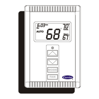
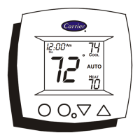
Explains the meaning of status indicators on the thermostat display.
Describes the initial display sequence when power is applied.
Lists and explains diagnostic codes displayed on the thermostat.
Provides common symptoms and their solutions for thermostat issues.
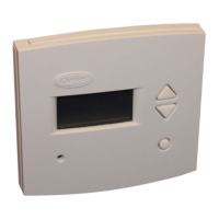
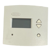
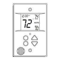
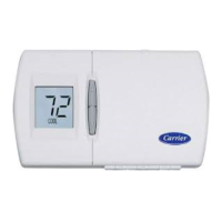
This document provides installation and operating instructions for Carrier Non-Programmable Thermostats, specifically models TSTATCCN(AC,HP,2S)01-C. These are wall-mounted, low-voltage thermostats designed to maintain room temperature by controlling heating and air conditioning systems.
The thermostats offer separate heating and cooling setpoints, along with an auto changeover feature for maximum comfort and flexibility. They are dual-powered, capable of operating with 24VAC (R and C terminals) or two AA batteries (included). Temperature and mode settings are preserved even without power.
Three distinct models are covered:
Configuration Options (Installer Settings): These options are typically set during installation and not modified by the homeowner. Accessing configuration mode involves holding the FAN button for approximately 15 seconds until "01" appears and the SERVICE icon illuminates. The thermostat automatically exits this mode after 3 minutes of inactivity.
Installer Test Mode: Initiated by pressing the FAN button for 20 seconds. "InS" appears, and the SERVICE icon illuminates. In this mode, the MODE button changes the system operating mode (AUTO mode is unavailable).
Outdoor Temperature Sensor Check: If equipped, pressing both the UP and DOWN temperature buttons simultaneously displays the outdoor temperature for about 5 seconds. "--" indicates a missing or improperly connected sensor.
Troubleshooting: The manual provides a troubleshooting table for common issues:
Filter Maintenance: The "Clean Filter Timer" (Option 02) helps remind users to check and replace filters based on blower operation hours. Recommended selections are: disposable filter (800 hr), media filter (1200 to 1600 hr), or electronic air cleaner (1600 to 2400 hr).
| Brand | Carrier |
|---|---|
| Model | TSTATCCNAC01-C |
| Category | Thermostat |
| Language | English |