moresecuremountingif needed.Makesureallwires
extendthroughholeinmountingbase.
7.Adjustlengthandroutingofeachwiretoreachproper
connectorblockandterminalonrearplasticwith1/4-in.
extralength.Striponly1/4in.ofinsulationfromeach
wireto preventadjacentwiresfromshortingtogether
whenconnected.
8.Matchandconnectequipmentwirestoproperterminalsof
eachconnectorblock.(SeeLowVoltageWiringDiagram
ReferenceChartandFigs.1through28inseparateWiring
Diagramliterature).RememberR andC mustbe
connectedfor properoperation.Improperwiringor
installationmaydamageThermidistatControl.Checkto
makesurewiringis correctbeforeproceedingwith
installationorturningonpower.
UNITDAMAGEHAZARD
Failuretofollowthiscautionmayresultinequipment
damageorimproperoperation.
Improperwiringor installationmay damage
ThermidistatControl.Checktomakesurewiringis
correctbeforeproceedingwithinstallationorturning
onpower.
9.Pushanyexcesswireintowallandagainstrearplastic.
Sealholeinwalltopreventairleaks.Leakscanaffect
operation.
10.ReattachThermidistatControlbodytorearplasticbyfirst
reattachinghinge.
11.CloseThermidistatControlassembly,makingsurepinson
backofcircuitboardalignwithsocketsinconnector.
12.Turnonpowertoequipment.
Onpowerup,alldisplaysegmentswilllightfor5sec.Forthe
next5 seca2-digitcodeappearsonlargedisplaywhich
identifiesThermidistatControlconfiguration.
1.AC--forl-stageairconditioner
2.HP--forl-stageheatpump
3.A2--for2-stageairconditioner
4.H2--for2-stageheatpump
5.dF--forl-stageHybridHeat
6.d2--for2-stageHybridHeat
7.HS--for1-stageheatpumpwithIntelligentHeatStaging
(3-stageauxiliaryheatwith40FK,FK4C,orFV4ASeries
fancoils.)
Whenthisidentifierdisappears,normaloperationbegins.The
MODEcontrolshouldbesettoOFFandFANcontroltoAUTO,
soequipmentdoesnotstartuntilfurtherconfigurationand
checkoutiscompleted.
Step4--Set Thermidistat ('ontrol ('onflguration
Configuration options, like DIP switch settings, are intended to
be selected at installation and normally are not modified by the
homeowner. These options are not discussed in the homeowner's
manual and therefore must be made as part of the installation. A
special procedure allows entry into the configuration mode.
While in configuration mode, up to 17 selections can be made.
Description of each selection and how to use the configuration
mode follows.
CONFIGURATION OPTIONS -- SUMMARY
Option 1--Anticipator adjustment
Option 2--Clean filter timer adjustment
Option 3--English/Metric selection
Option 4--Fan (G) ON with W selection
Option 5--Variable-speed blower present selection
Option 6--Cooling lockout below 55 ° selection
Option 7--Variable-speed super dehumidification selection (only
available when variable-speed blower is used)
Option 8--Auxiliary heat lockout temperature setting (only
available when heat pump is used)
Option 9--Intelligent Heat Staging selection (only available
when single-stage heat pump is used)
Option 10--Hybrid Heat selection (only available when heat
pump is used)
Option 11--Balance point setting (only available when Hybrid
Heat is selected)
Option 12--Defrost heat selection (only available when heat
pump is used)
Option 13--Room temperature offset adjustment
Option 14--Heat/cool dead band adjustment
Option 15--Enable Auto mode
Option 16--Enables Super Comfort Heat Mode
Option 17--Non-Programmable selection
TO ENTER CONFIGURATION MODE
Press and hold FAN button for approximately 10 sec until COOL
set point display indicates a flashing 1. The Thermidistat
Control is now in configuration mode. It will automatically exit
this mode if no button is pressed for 3 minutes. Pressing END
button will exit configuration mode immediately.
WHILE IN CONFIGURATION MODE
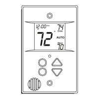
The upper small (COOL set point) display indicates selected
option number and large display indicates selection made within
that option. One of these will be flashing. The up and down
buttons are used both to move between available options and to
make selection for each option. When option number (small
display) is flashing, up and down buttons adjust it, moving
between available option numbers. After desired option number
has been selected, press SET TIME/TEMP button once. The large
display will now flash, indicating that up and down buttons now
control available choices within that option. Each press of
TIME/TEMP button switches between available option (small
display) and available selections within each option (large
display).
CONFIGURATION OPTIONS --SELECTION
Option 1--Anticipator Adjustment
This adjustment controls sensitivity and cycle rate of Thermidistat
Control. Higher numbers decrease sensitivity and slow cycle rate.
Lower numbers increase sensitivity and cycle rate. However, a
limiting feature 'sTill not allow more than 4 cycles per hr,
regardless of setting. Anticipator values can range from 1 to 9.
Factory default is 3. This default selection provides optimum
performance in nearly all installations. Try it first. Do not change
setting unless there is evidence of need to do so. Unlike
conventional anticipators, this setting is not determined by current
draw. There is no need to measure, know, or compensate for
current draw. There is also no droop with this Thermidistat
Control. Regardless of setting and number of stages, both heating
and cooling will control to their respective set points.
TO ADJUST
1. Enter configuration mode if not already there. See Step 4
"To Enter Configuration Mode." The upper small (COOL
set point) display will be flashing 1. If not, use up and
down buttons to move it to 1.

 Loading...