GB - 7
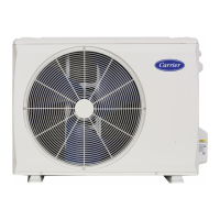
38VYX110/38VYX130
ENGLISH
Minimum clearances
Open the upper side and both right and left sides.
The height of obstacle at both front and rear side, should be lower than the height of the outdoor unit.
1000
or more
150
or more
Serial installation of two or more units
1000
or more
1500
or more
2000
or more
200
or more
300
or more
Obstacles at both front and rear sides
Standard installation
Single unit installation
300
or more
200
or more
300
or more
1000
or more
Open the upper side and both right and left sides.
The height of obstacle at both front and rear side, should be lower than the height of the outdoor unit.
Serial installation at front and rear sides
Standard installation
38 VYX 110-130
Installation
• Before installation, check strength and horizontality of the base so
that abnormal sound does not generate.
• According to the following base diagram, fix the base firmly with
the anchor bolts.
(Anchor bolt, nut: M10 x 2 pairs)
15 mm or less
• Set the out margin of the anchor bolt to 15mm or less..
Drain
hole
Knockout
hole
Drain nipple
mounting hole
600
150
150
430
400
365

 Loading...
