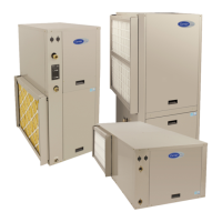
GC Series
Geothermal Heat Pump
Sizes 024, 036, 048, 060, 072
Installation Instructions
NOTE: Read the entire instruction manual before starting the installation.
TABLE OF CONTENTS
PAGE NO.
SAFETY CONSIDERATIONS 2.....................
INTRODUCTION 2...............................
APPLICATION CONSIDERATIONS 3...............
Geothermal Systems 3...........................
Well Water Systems 4............................
INSTALLATION RECOMMENDATIONS 6...........
MOUNTING VERTICAL UNITS 6...................
MOUNTING HORIZONTAL UNITS 6................
CONDENSATE DRAIN 7...........................
DUCT SYSTEM 7.................................
Air Ducts 7....................................
PIPING 7........................................
PIPING & PLUMBING INSTALLATION 8............
Loop Pump Connections 8........................
Water Solenoid Valves 8.........................
Flow Regulator Valve 8..........................
Typical Open Loop Piping 9......................
Utility Curtailment 12...........................
Energy Tracking 12.............................
FACTORY INSTALLED OPTIONS 12................
Heat Recovery Package (HRP) 12..................
ELECTRICAL 14.................................
Electrical Connections 14.........................
Low-- Voltage Circuit Fusing and Reference 14........
Ground Connections 14..........................
ELECTRONIC THERMOSTAT INSTALLATION 15...
Communicating 15.............................
Non-- Communicating (Emergency Mode Only) 15.....
FIELD INSTALLED COMPONENTS 16..............
Electric Heaters 16..............................
Outdoor Air Temperature Sensor 16................
Outdoor Air Thermistor 17.......................
Electronic Air Cleaner Connections 17..............
Humidifier Connections 17.......................
System Shutdown Accessories 17..................
Generator 17..................................
Ventilation Accessory 17.........................
Compressor Start Accessories 17...................
TIMER SPEEDUP (TEST MODE) 18.................
PAGE NO.
PRE START-- UP CHECKLIST 18...................
USER INTERFACE QUICK S ET--UP 18..............
SYSTEM INITIAL POWER UP AND CHECKOUT 18..
SYSTEM VERIFICATION 19.......................
MAIN CONTROL BOARDS 19......................
UPM Board 19.................................
UPM Sequence of Operation 22....................
ECM Board 23.................................
ECM Sequence of Operation 23....................
OPERATING TEMP. AND PRESSURES TABLES 25...
AUXILIARY HEAT LOCKOUT 24..................
BLOWER AIRFLOW DELIVERY CHART 30.........
WATER SIDE PRESSURE DROP TABLE 30..........
BLOWER PERFORMANCE DATA TABLE 31........
INITIAL STAR--UP OF HRP SYSTEM 32.............
SYSTEM FUNCTION & SEQ. OF OPERATION 33.....
Communications and Status Function Lights 33.......
Time Delays 33................................
Compressor Operation 33........................
Troubleshooting units for proper switching between
low and high stages 33.........................
Unloader Test Procedure 33.....................
Two Stage Compressor 33......................
Compressor Internal Pressure Relief (IPR) 33........
Compressor Control Contactor 33.................
Troubleshoot Compressor 33....................
TROUBLESHOOTING 34..........................
UPM Fault Code Table 34........................
ECM BOARD TROUBLESHOOTING 36...........
LED Description & Fault Code Table 35...........
ECM Blower Start-- up & Troubleshooting 36........
Emergency Heating & Cooling Modes 36...........
ECM Board Start-- Up &
System Comm. Troubleshooting 36...............
ECM Board Status (Fault) Codes 36...............
ECM MOTOR TROUBLESHOOTING 36...........
SYSTEMS COMMUNICATION FAILURE 39.......
MODEL PLUG 39.............................
SERVICE TOOL 39............................
10K Temperature Sensor Resistance Table 40.........
CONFIGURATIONS 41............................
MAINTENANCE 45...............................
