41
CONFIGURATIONS
Horizontal Configuration
Horizontal units can be field converted from end--discharge to side--discharge or vice versa.
See table below for kit number required for unit conversion. Conversion Instructions are included in the kits.
Table 1 8 – Horizontal Unit Conversion
GC Original Configuration Converted Configuration Kit
Model View Return Supply View Return Supply Required
024
A Left Right C Left End 8 --- 7 3 3 --- 9 4 2 --- 9 6 0
B Right Left D Ri ght End 8 --- 7 3 3 --- 9 4 2 --- 9 6 1
C Left End A Left Right 8 --- 7 3 3 --- 9 4 2 --- 9 6 6
D Right End B Right Left 8 --- 7 3 3 --- 9 4 2 --- 9 6 7
036 --- 048
A Left Right C Left End 8 --- 7 3 3 --- 9 4 2 --- 9 6 2
B Right Left D Ri ght End 8 --- 7 3 3 --- 9 4 2 --- 9 6 3
C Left End A Left Right 8 --- 7 3 3 --- 9 4 2 --- 9 6 8
D Right End B Right Left 8 --- 7 3 3 --- 9 4 2 --- 9 6 9
060 --- 072
A Left Right C Left End 8 --- 7 3 3 --- 9 4 2 --- 9 6 4
B Right Left D Ri ght End 8 --- 7 3 3 --- 9 4 2 --- 9 6 5
C Left End A Left Right 8 --- 7 3 3 --- 9 4 2 --- 9 7 0
D
Right End B Right Left 8 --- 7 3 3 --- 9 4 2 --- 9 7 1
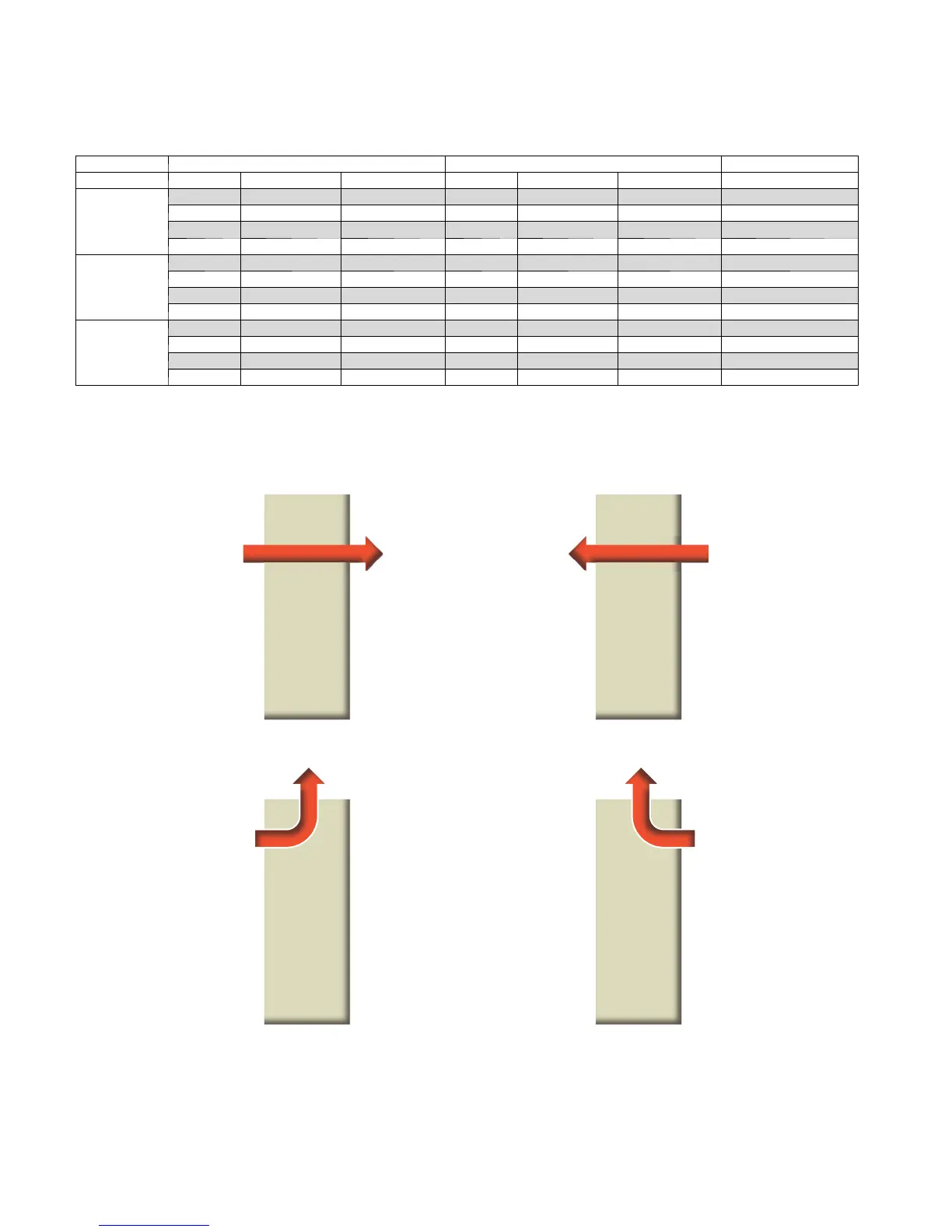
Left Return Right Return
Front
Front
Front
Front
Side Discharge
End Discharge
Notes:
"Front" of horizontal unit is location of water lines and electrical box.
When converting end discharge (C & D) to side discharge (A & B), auxiliary heat is mounted externally
B
CD
TOP VIEWS, HORIZONTAL UNITS
Arrows indicate airflow direction
A160134
 Loading...


