23
ECM BOARD
SEC-1
SEC-2
FUSE 3AMP
HEATER
STATUS
COMM
OAT
MOTOR
HPT
HUM C O Y W G R
OPN
COM
CLS
1
2
3
4
5
6
7
8
10
11
A150556
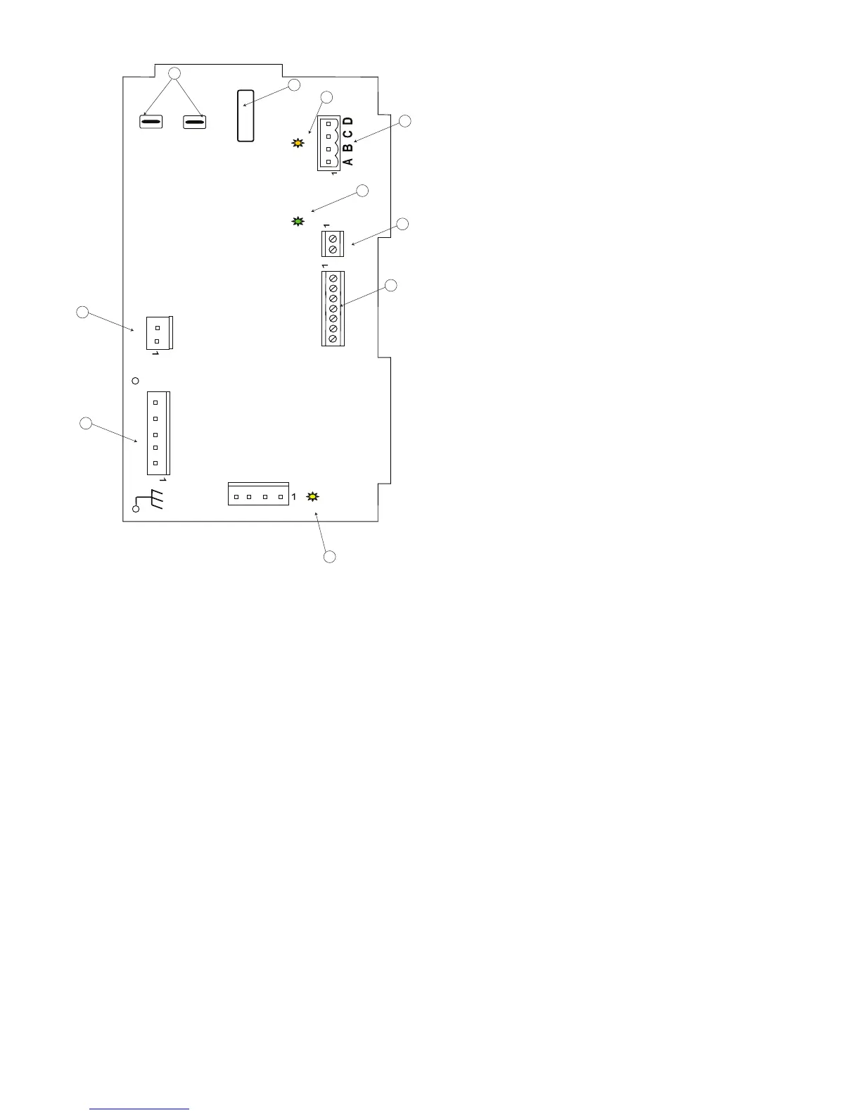
(1) SEC 1 and SEC 2 (7) Non--comm. t--stat emergency only
connections
(2) Transformer Power (8) Motor Power Indicator Light
(3) Status LED Light (9)
(4) ABCD Communicating Thermostat
Terminal Plug Connection.
(10) Heater Connection f or Field
Supply Electric Heat
(5) COMM Light (11) HPT
(6) OAT -- Outdoor Air Temp Sensor
Fig. 28 -- Detail of ECM Printed Circuit Board Connections
NOTE: CFM LED indication is an approximation. Utilize
conventional Test and Balance equipment for accurate airflow
measurement.
SCFM count indicator (see Fig. 28, item 6) blinks to indicate
approximate airflow in CFM and may flicker when the unit is off.
SEach blink of the LED represent approximately 100 CFM of air
delivery so if the LED blinks 12 times, pauses, blinks 12 times, etc.
the blower is delivering approximately 1200 CFM.
SAn annual “checkup” is recommended by a qualified refrigeration
mechanic.
SRecording the performance measurements of volts, amps, and water
temperature differences (both heating and cooling) is recommended.
This data should be compared to the information on the unit’s data
plate and the data taken at the original start-- up of the equipment.
SPeriodic lockouts are commonly caused by water flow problems.
The lockout (shutdown) of the unit is a normal protective measure in
the design of the equipment. If continual lockouts occur, call a
mechanic immediately and have them check for the following:
-- Water flow problems
-- Water temperature problems
Unit capacity and water flow charts should be used for system
checks. Refer to Table 9.
Using the Owner’s/User Manual furnished with unit, the installing
technician should explain system operation to the consumer with
particular emphasis on indoor fan coil operation sounds and filter
maintenance.
ECM Sequence of Operation
The GC is designed for installation with a communicating User
Interface. This blower will not respond to commands provided by a
common thermostat except under certain emergency situations
described in Blower Start Up and Troubleshooting section of this
document.
The User Interface uses temperature; humidity and other data
supplied from system components to control heating or cooling
system for optimum comfort. The blower will be commanded by
User Interface to supply airflow. The blower will operate at
requested airflow for most modes.
The nominal requested airflow will be 350 cfm per ton of nominal
cooling capacity as defined by unit size. Actual airflow request will
be adjusted from nominal using indoor and outdoor temperature
and indoor humidity data to optimize the system operation for
occupant comfort and system efficiency. Refer to User Interface
literature for further system control details.
Airflow during electric heater operation must be greater than a
minimum level for safe operation. If User Interface instructs blower
to turn on electric heat and the requested airflow is less than the
minimum value required for safe operation of installed heater, the
ECM board will override requested value with the value shown in
Table 10, Blower Airflow Delivery Chart -- Electric Heating
Modes.
 Loading...


