17
A150195
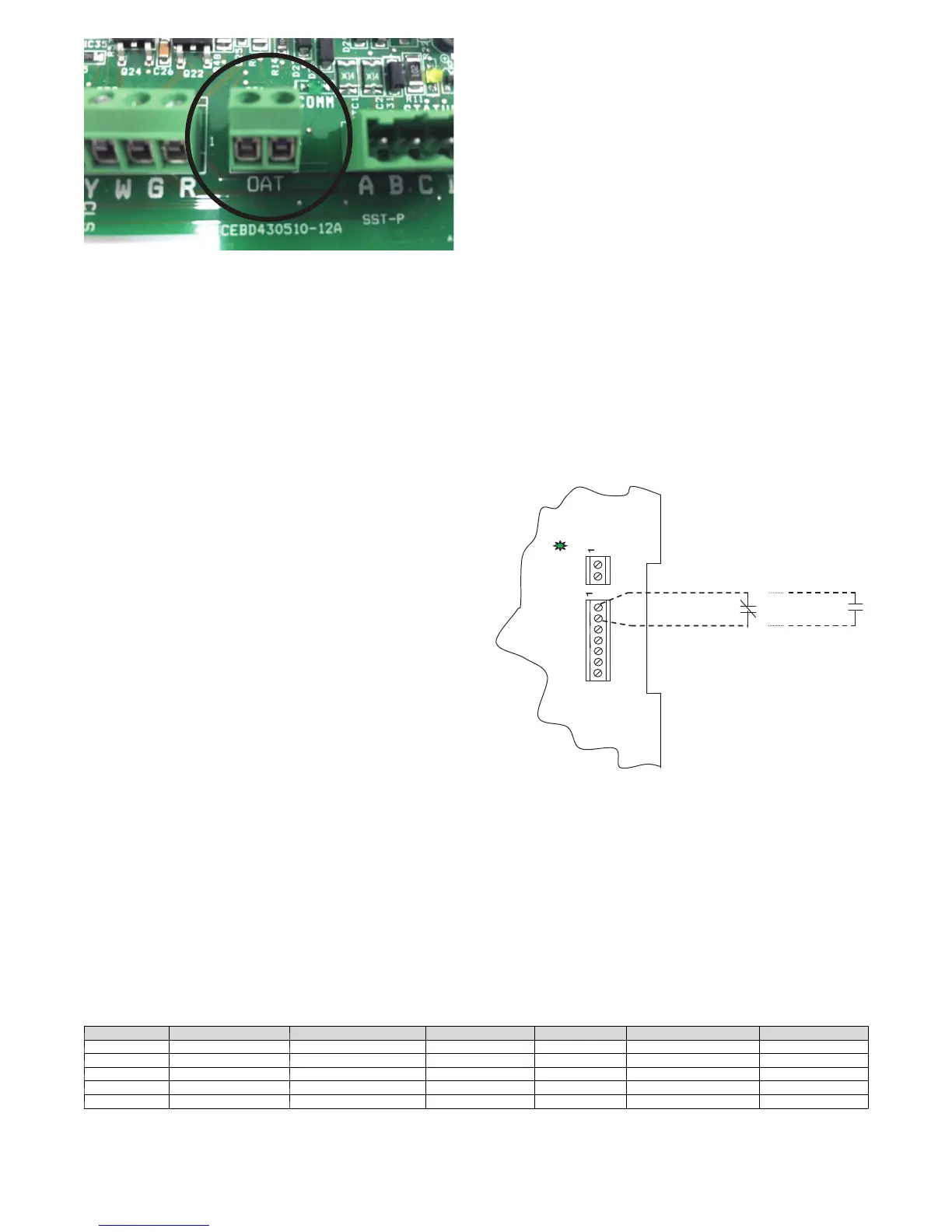
Fig. 20 -- OAT Sensor Connection
Outdoor Air Thermistor
A 2 -- screw terminal strip is provided for connection of an outdoor
temperature thermistor. The installation of an outdoor temperature
sensor using the ECM board terminals is optional. OAT input can
be used to supply outdoor temperature data for system level
functions and for temperature display on User Interface. If an OAT
is added, it will be used for system level functions.
Using two wires of field--supplied thermostat wire cable, wire one
lead of thermistor to one screw terminal and the other lead to
remaining screw terminal; there is no polarity to be observed. It is
strongly recommended that two wires be used to connect the
thermistor to eliminate noise interference in temperature reading. If
there are not two spare wires available in cable, one wire may be
used to connect thermistor to OAT screw terminal 1 and the other
lead of the thermistor can be wired to 24VAC COM (C) wire. OAT
screw terminal 1 is terminal located closest to the ABCD system
communications and is marked with a small number 1 next to the
terminal strip.
NOTE: Mis--wiring OAT inputs will not cause damage to either
ECM board or thermistor. If the thermistor is wired incorrectly, no
reading will appear at User Interface. Re--wire thermistor correctly
for normal operation.
Electronic Air Cleaner Connections
When using an electronic air cleaner, use airflow sensor part no.
KEAAC0101AAA. The airflow sensor turns on electronic air
cleaner when blower is operating.
Humidifier Connections
The ECM board terminal marked “HUM” is provided for low
voltage (24VAC) control of a humidifier. No humidistat is required
as User Interface monitors indoor humidity. When commanded to
operate humidifier, the ECM board will ener gize the “HUM”
output to turn humidifier on and de-- energize HUM output to turn
humidifier off. Wire “HUM” and “C” terminals directly to
humidifier as shown in Fig. 18 or 19.
System Shutdown Accessories
The G thermostat terminal input can be configured through the
User Interface to recognize accessories that will shut the system
down in response to a malfunction. The ECM board can be
configured to recognize either Normally Open or Normally Closed
(default) contact devices through the User Interface Set-- Up
screens. Wire the accessory device contacts in series with the R and
G thermostat connections at the ECM board board. The User
Interface will respond to the accessory device signal by ordering a
shutdown of the system and will display SYSTEM
MALFUNCTION on its screen. Refer to the User Interface
Installation Instructions for more detail. See Fig. 21.
Generator
The ECM board G thermostat terminal input can be configured
through the User Interface to recognize a Generator Normally
Open dry-- contact output to signal the system that a generator
malfunction condition exists. Wire the generator output in series
with the R and G thermostat connections at the ECM board. The
User Interface will display GENERATOR MALFUNCTION when
the G thermostat input is energized. This function requires the
addition of a Generator Self Test Verifier (Part No. GSV200) which
must be purchased separately. V isit www.GeneratorVerifier.com for
details and ordering information. Refer to the User Interface
Installation Instructions for more detail. See Fig. 21.
Ventilation Accessory
The G thermostat terminal input can be configured through the
User Interface to recognize a Normally Open dry--contact output to
signal the system that a Ventilation Accessory requires blower
operation. Blower operation can be configured for Low, Med or
High speed when the G terminal is ener gized. Wire the Accessory
output in series with the R and G thermostat connections at the
ECM board. Refer to the User Interface Installation Instructions for
more detail. See Fig. 21.
COMM
OAT
HUM C O Y W G R
CLS
OPN
COM
System
Shutdown
Device
System
Shutdown
Device
or
Generator
or
VentilationAccessor
A07121
Fig. 21 -- “G” Terminal Accessory Wiring
Compressor Start Accessories
In the event of the rare occurrence of compressor starting issues
such as dimming of the residential lights. Verify and correct
voltage issues and add hard start components. Table 7 lists Hard
Start components that are recommended in areas of poor power
conditions.
Table 7 – Recommended Hard Start Kits
Unit Size Compressor Hard Start Kit Start Cap Start MFD Start Cap Volts Start Relay
GC024 ZPS20K5E ---PFV KSAHS2501AAA HC95DE088 88---108 330 HN61HB540
GC036 ZPS30K5E ---PFV KSAHS2501AAA HC95DE088 88---108 330 HN61HB540
GC048 ZPS40K5E ---PFV KSAHS2801AAA HC95DE088 88---108 330 HN61HB553
GC060 ZPS51K5E ---PFV KSAHS2801AAA HC95DE088 88---108 330 HN61HB553
GC072 ZPS60K5E ---PFV N/A N/A 43 330 HN61HB553
 Loading...


