34
TROUBLESHOOTING
IMPORTANT: The follo wing Troubleshooting tables are designed to help identify possible causes and solutions for problems. There
could be more than one cause/solution to a problem that can be applied. Check each cause and adopt ”process of elimination”
and/or verification of each before making a conclusion.
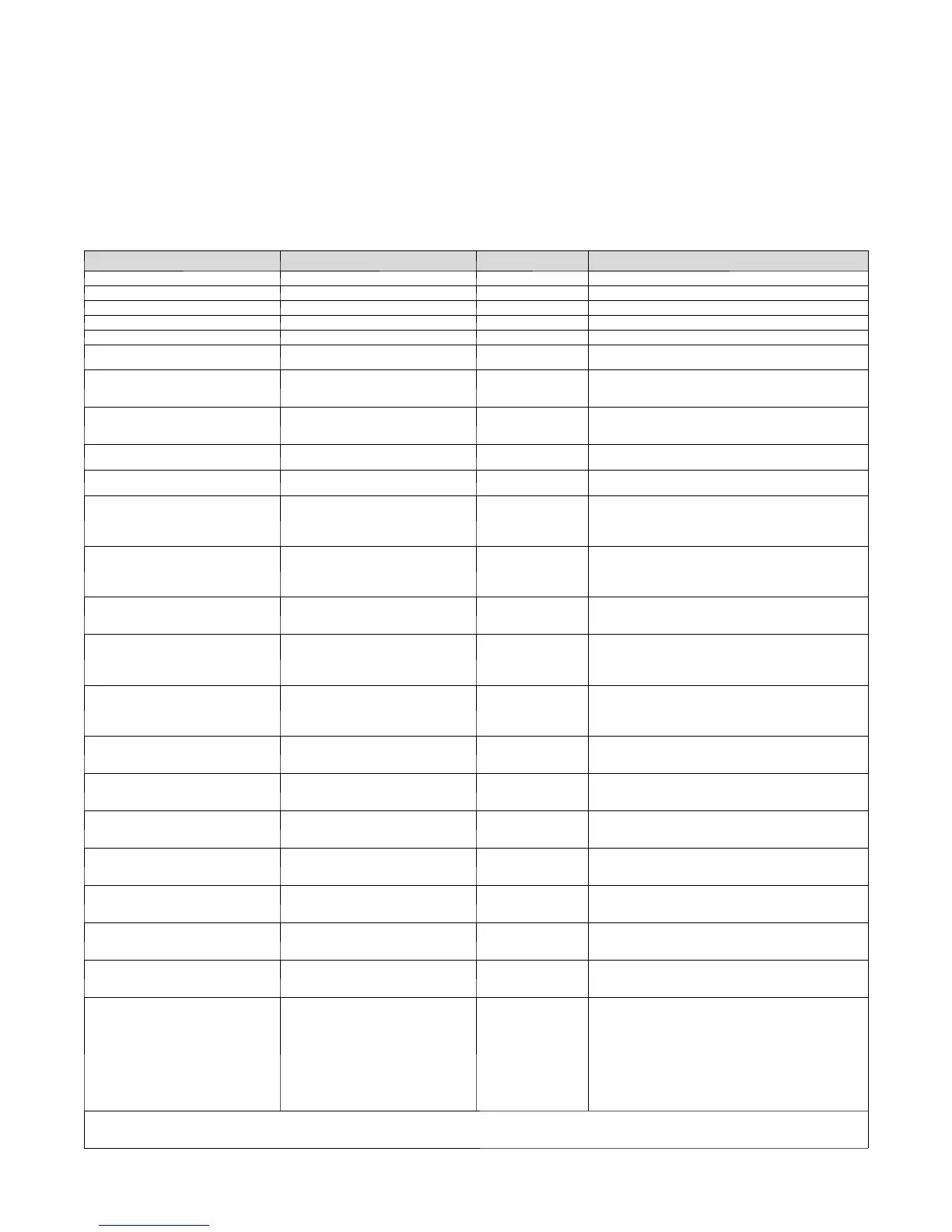
Tables 14 and 15 show the status codes flashed by the amber status
light. The codes are flashed by a series of short and long flashes of
the status light. The short flashes indicate the first digit in the
status code followed by long flashes indicating the second digit of
the error code. The short flash is 0.25 seconds on and the long
flash is 1.0 seconds on. Time between flashes is 0.25 seconds.
Time between short flash and first long flash is 1.0 seconds. Time
between code repeating is 2.5 seconds with LED off.
Table 14 – UPM Fault Code Table
OPERATION FAULT FLASH CODE POSSIBLE CAUSE AND ACTION
Standby 18---30 VAC power is present ON, no flash Normal Operation
Low Stage 1, pause Normal Operation
High Stage 2, pause Normal Operation
Brownout Protection is Disabled 5, pause User made selection, see instructions for details
Brownout Protection is Active 6, pause Default, user can disable see instructions for details
System Communication Failure 16
Communication with User Interface lost. Check wiring
to and from User Interface
Invalid Model Plug 25
Control does not detect a model plug or detects an
invalid model plug. Unit will not operate without cor-
rect model plug.
High Pressure Switch 31*
High Pressure Switch T rip. Check Refrigerant
Charge, Water Flow and Temperature too h igh in
cooling, and airflow restrictions in heating.
Low Pressure Switch 32*
Low Pressure Switch T rip. Check Refrigerant Charge,
TXV operation and airflow restrictions.
Internal Board Failure 45
UPM board has failed. Replace Board and transfer
model plug to replacement board.
Brownout on 230V 46
Line vol tage <170V for at least 4 seconds. Compres-
sor and blower not allowed until voltage >173V. Veri-
fy line voltage. This feature can be disabled, see in-
structions for details.
No 230V to unit 47
There is no 230V at the contactor when indoor unit is
powered and cooling/heating demand exists. Verify
the disconnect is closed a nd 230V wiring is connect-
ed to the unit.
Freeze Sensor Fault 57
Freeze sensor is invalid or out of range.. Check for
open sensor, wire disconnected, sensor not connect-
ed properly or abnormal sensor temp ranges.
Compressor Thermal Cutout
in Low Stage
71*
Compressor operation detected then disappears
while low stage demand exist. Possible causes are
internal compressor overload trip or start relay and
capacitor held in circuit too long (if installed).
Compressor Thermal Cutout
in High Stage
72*
Compressor operation detected then disappears
while high stage demand exist. Possible causes are
internal compressor overload trip or start relay and
capacitor held in circuit too long (if installed).
Voltage at Standby
(contactor shorted)
73
Compressor voltage sensed when no demand for
compressor operation exists. Contactor may be
stuck closed or there is a wiring error.
No Voltage to Compressor
(No voltage at start---up)
74
Compressor voltage not sensed when compressor
should be starting. Contactor may be stuck open or
there may be a wiring error.
Thermal Lockout in Low Stage
for 4 Hours
81
Thermal cutout occurs in 3 consecutive low/high
stage cycles. Low stage locked out for 4 hours or
until 24V power recycled.
Thermal Lockout in High Stage
for 4 Hours
82
Thermal cutout occurs in 3 consecutive high/low
stage cycles. High stage locked out for 4 hours or
until 24V power recycled.
Low Pressure Lockout 83
Low Pressure Switch (LPS) trips 2 or 4 times in an
hour. Unit operation is locked out for 4 h ours or until
24V power recycled.
High Pressure Lockout 84
High Pressure Switch (HPS) trips 2 or 4 times in an
hour. Unit operation is locked out for 4 h ours or until
24V power recycled.
Condensate Overflow 85
Waterinthecondensatepanexceedscertainlevel.
The compressor is re ---ener gized when water issue
clears.
Freeze Sensor Lockout 86
Refrigerant temperature drops below or remains at
freeze limit trip for 30 seconds, the unit enters into a
permanent lockout an d needs a manual reset. Water
coil freeze sensor below limit, verify proper loop wa-
ter temp and pressures. Verify sensor accuracy us-
ing tables in instructions and verifying it is properly
attached to coil. Verify antifreeze quantity if applica-
ble and the freeze protection limit dip switch settings
appropriate on the UPM board.
*Sequence: Compressor contactor is de---energized. If demand still exists, control will energize compressor contactor after 15 minute delay. If fault is
cleared, unit will resume operation. If fault exists, blower shuts off, and error code continues to flash. Control will attempt re---start every 15 minutes. Cycling
low voltage defeats the 15 minute delay.
 Loading...


