GB // Instruction Manual
Meaning of the symbol on the product, packaging or instructions for use: Electrical appliances contain valuable recyclable materials and
should not be discarded in the domestic waste at the end of their service life! Help us protect the environment and conserve resources by
taking this appliance to the appropriate local recycling centre. Your local waste management organisation or specialist dealer will be able to
answer any queries you may have.
The switch modules are connected directly to a RC receiver and can be controlled via a push-button, switch or joystick. The position of the switch (up and
down) and the duration (short and long) are evaluated here. In the case of the 2-way module, only the position is evaluated. It should be noted that the
push-buttons and switches have a middle position. Every switching output has a memory function, i.e. it remains activated until the switch has been
returned to the neutral position and then brought into the same position again. The number of separate negative switching outputs available on the switch
modules is 4 and 2 respectively. Each of the outputs has a blue lead 20cm in length. This lead must be connected to the consumer’s negative terminal. Each
switching output can switch a maximum current of up to 2.5A. The maximum permissible supply voltage is 16 V. The switching module draws its supply
from the voltage on the servo cable. The black negative lead can be connected directly to the battery or to the distribution terminal. With high loads it is
imperative to connect the black lead to avoid damage to the receiver.
SWITCH MODULES
TECHNICAL DATA
Input voltage: 4 - 8V from the receiver
Input current: Approx. 18mA at 5V
Outputs: 2 or 4 off
Switching voltage: Maximum 16V
Switching current: Maximum 2.5A per output
Connecting leads: Outputs: 2/4 blue silicone leads each 200mm in
length and 0.25 mm²
Servo connection: 300 mm servo lead with UNI
connector
Negative lead: Silicone lead 200 mm in length
and 0.5 mm²
Dimensions: 16 x 14 x 4 mm
Weight: 10 g
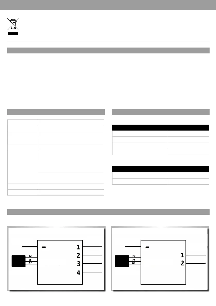
4-way module:
PIN ASSIGNMENT
SWITCHING ACTION
4-way module:
2-way module:
Switch position Outputs
Long in "top” position Output 1
Short in "top” position Output 2
Short in "bottom” position Output 3
Long in "bottom” position Output 4
Switch position Outputs
Short in "top” position Output 1
Short in "bottom” position Output 2
Outputs 1 to 4
Minus Minus
Receiver Receiver
Servo cable Servo cable
2-way module:
Outputs 1 to 2