switched
in, and
left
in.
This
can
give
you
music
and
programming
that's unbelivably clean
and
quiet, without
a
hint
of
annoying distortion
and
noise. With
the
noise reduction features
of the
Asymmetrical
Charge-Coupled
FM
Detector,
FM
stereo listening
on
cable feed,
in
many
cases,
will
rival
or
exceed
the
noise performance
of
your tapes
(cassettes, reel-to-reel, etc.),
in
terms
of
audio
quality.
Muting Time
When
either
the
NOISE REDUCTION
or
MULT1PATH
REDUCTION
switches
are
engaged,
a
logic
system analyzes
the
signal
for
multipath and/or noise content. This process requires about
3
/4
of a
second. Whenever
a new
station selection
is
made,
the
mute time
is
about
1
/2
second.
If a new
station
is
selected
AND
either
the
NOISE
REDUCTION
or
MULTIPATH REDUCTION switch
is
simultaneously
engaged
OR has
already been engaged,
the
muting times
are
additive:
3
A
+
1
/2
=
1
1
/4
seconds.
Antennas
Sending information through
the
air,
as
part
of
basic
radio
broadcasting,
is a
relatively simple process.
At
the
broadcaster's end,
the
set-up includes
a
studio,
transmitter,
and
transmitting antenna.
The
studio supplies program materials (music, drama, news, etc.)
to
the
transmitter. Acting
as a
giant amplifier
of
sorts,
the
transmitter
sends
the
signal
at
high power
and a
specific frequency
on to the
transmitting antenna
in the
form
of
alternating
current.
This
creates
an
electromagentic field that propagates through
the
air.
At
your end,
the
listener's end,
a
length
of
wire
is set up for use as a
receiving
antenna. When
the
electromagnetic
fieid
generated
by the
transmitter/transmitting antenna combination reaches
the
wire,
a
small
AC
current
is
induced
in it. A
tuner connected
to
this wire,
or
receiving antenna, translates this small current back into
a
"usable"
form.
In
short, back into music, drama,
and
other programs
for
your
enjoyment.
Of
course,
this
description
of
what goes
on in the
transmission part
of
radio broadcasting
has
been greatly
over-simplified.
There's
a lot
going
on in the
actual transmission
of
stereo signals,
and
you'll soon
discover
there's
a lot
going
on at
your
end
when
it
comes
to
that
"length
of
wire"
or
receiving antenna. This chapter
is an
in-depth
discussion
of how you can
obtain
the
best signal possible
for the TX-
11
b
through selection
and
installation
of an
antenna system.
At the
same
time,
we
offer
some alternatives
and
ideas,
so you can
choose
a
system that's
not
only right
for the
TX-11
b, but
right
for you and
your
locale.
We'll
be
looking
at the
three major topics that concern receiving
antennas: antenna configurations,
installing
the
antenna,
and the
feedline from
the
antenna
to the
TX-11
b. Of
course,
if
you've decided
to
have
a
company distribute
TV and FM
programming
to
your home
via
cable,
the
following information
may be of
passing interest only.
Skip
ahead
to the
CABLE section
at the end of
this chapter.
If
you'd
like
to
know more about antennas,
the
benefits
of a
quality antenna,
and
some
of the
causes
and
cures
for
multipath, please read
on!
FM
Antennas
Configurations
To
begin this look
at
receiving antennas,
we
must first establish
a
reference
for
comparing
different
antennas.
Our
reference
antenna
will
be a
half-wave dipole, just like
the one
that came with
the
TX-11
b.
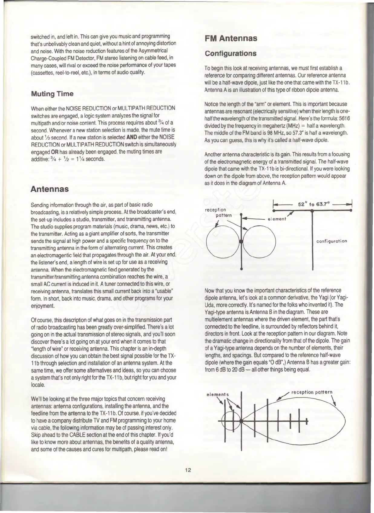
Antenna
A is an
illustration
of
this type
of
ribbon dipole antenna.
Notice
the
length
of the
"arm"
or
element. This
is
important because
antennas
are
resonant (electrically sensitive) when their length
is
one-
half
the
wavelength
of the
transmitted
signal.
Here's
the
formula:
5616
divided
by the
frequency
in
megahertz (MHz)
=
half
a
wavelength.
The
middle
of the FM
band
is 98
MHz,
so
57.3"
is
half
a
wavelength.
As
you can
guess,
this
is why
it's
called
a
half-wave
dipole.
Another
antenna characteristic
is its
gain.
This results
from
a
focusing
of
the
electromagnetic
energy
of a
transmitted
signal.
The
half-wave
dipole that came with
the
TX-11
b is
bi-directional.
If you
were looking
down
on the
dipole from above,
the
reception pattern would appear
as it
does
in the
diagram
of
Antenna
A.
reception
pattern
52"
to
63.7"
configuration
Now
that
you
know
the
important characteristics
of the
reference
dipole antenna, let's look
at a
common derivative,
the
Yagi
(or
Yagi-
Uda,
more correctly.
It's
named
for the
folks
who
invented
it).
The
Yagi-type antenna
is
Antenna
B in the
diagram. These
are
multielement antennas where
the
driven element,
the
part that's
connected
to the
feedline,
is
surrounded
by
reflectors behind
it,
directors
in
front. Look
at the
reception pattern
in our
diagram. Note
the
dramatic change
in
directionality from that
of the
dipole.
The
gain
of
a
Yagi-type antenna depends
on the
number
of
elements, their
lengths,
and
spacings.
But
compared
to the
reference
half-wave
dipole (where
the
gain equals
"0
dB",)
Antenna
B has a
greater gain:
from
6 dB to 20 dB — all
other things being
equal.
reception pattern
12


 To Next Page
 Loading...
