2
6
5
1
3
4
4
13
7
10
9
12
11
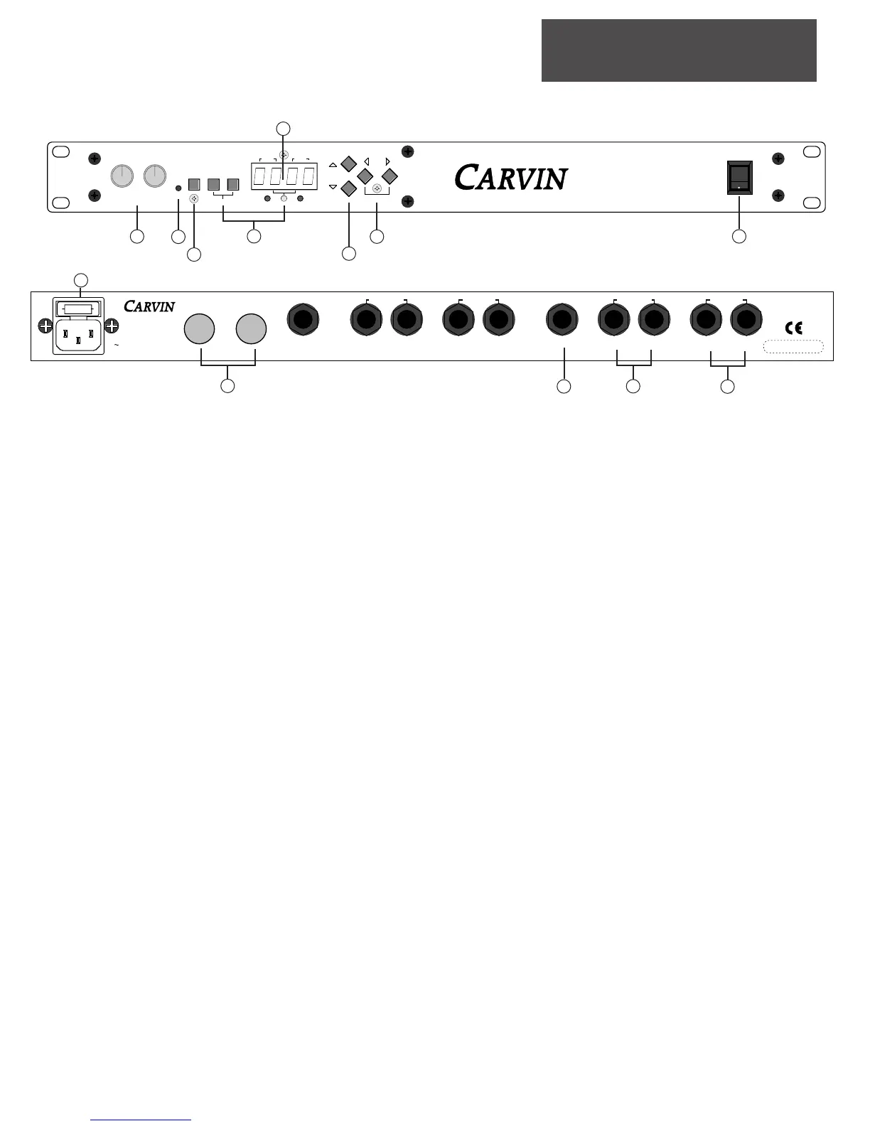
FRONT PANEL
1. INPUT AND OUTPUT LEVELS
The input and output level controls are stereo level controls adjusting both
the EFF1 and EFF2 engines at the same time. When adjusting the input level
control be sure to watch the clip LED to prevent overloading the input.
2. CLIP INDICATOR
The red CLIP LED indicator will start to flash when the input signal is near
maximum (6db below distortion levels). To avoid clipping, decrease the
INPUT level.
3. BYPASS/SHIFT
Disengages the effect when pressed. Acts as a shift button for the com-
pare and global parameters.
4. EFF1, EFF2 SWITCHES AND LED INDICATORS
These switches select the individual effect engines for editing and chang-
ing effects. When both of these buttons are pressed together, the two effect
engines function as one STEREO engine. The EFF1, EFF2 and STEREO
LEDs indicate which engine is selected and if they are in STEREO mode.
5. PARAMETER DISLPAY
Displays the effect assigned to EFF1 & EFF2. Also displays the edit para-
meters.
6. VALUE , GLOBAL & COMPARE
These buttons are used for
scrolling through the effects and editing effect parameters.
7. EDIT
Selects the parameters to edit.
8. POWER SWITCH
The XP series of processors do a brief initialization when powered on.
This is indicated by “----“ on the displays while this is being done.
REAR PANEL
9. AC FUSE & AC POWER
The XP series processors have a switching power supply circuit capable
of accommodating all voltages from 95-250 VAC.
10. MIDI IN & MIDI THRU
Standard MIDI Patches. See MIDI section for more information.
11. FOOTSWITCH JACK
The footswitch jack is designed to accept a footswitch (like Carvin’s FS22)
with a stereo or mono 1/4” plug. See the Global Parameters section for more
information.
12. OUTPUTS 1/2
When the XP2/XP4 is in stereo mode, these 1/4” jacks are stereo L/R out-
puts from the effect processor. When the unit is in dual mono mode these
are outputs from two separate mono effects.
13. INPUTS 1/2
While in dual mono mode, EFF1 & EFF2 are mono 1/4” inputs. When in
STEREO mode, EFF1 & EFF2 become the STEREO LEFT and EFF2 becomes
the STEREO RIGHT input.
XP2 FRONT
XP4 REAR
3
 Loading...