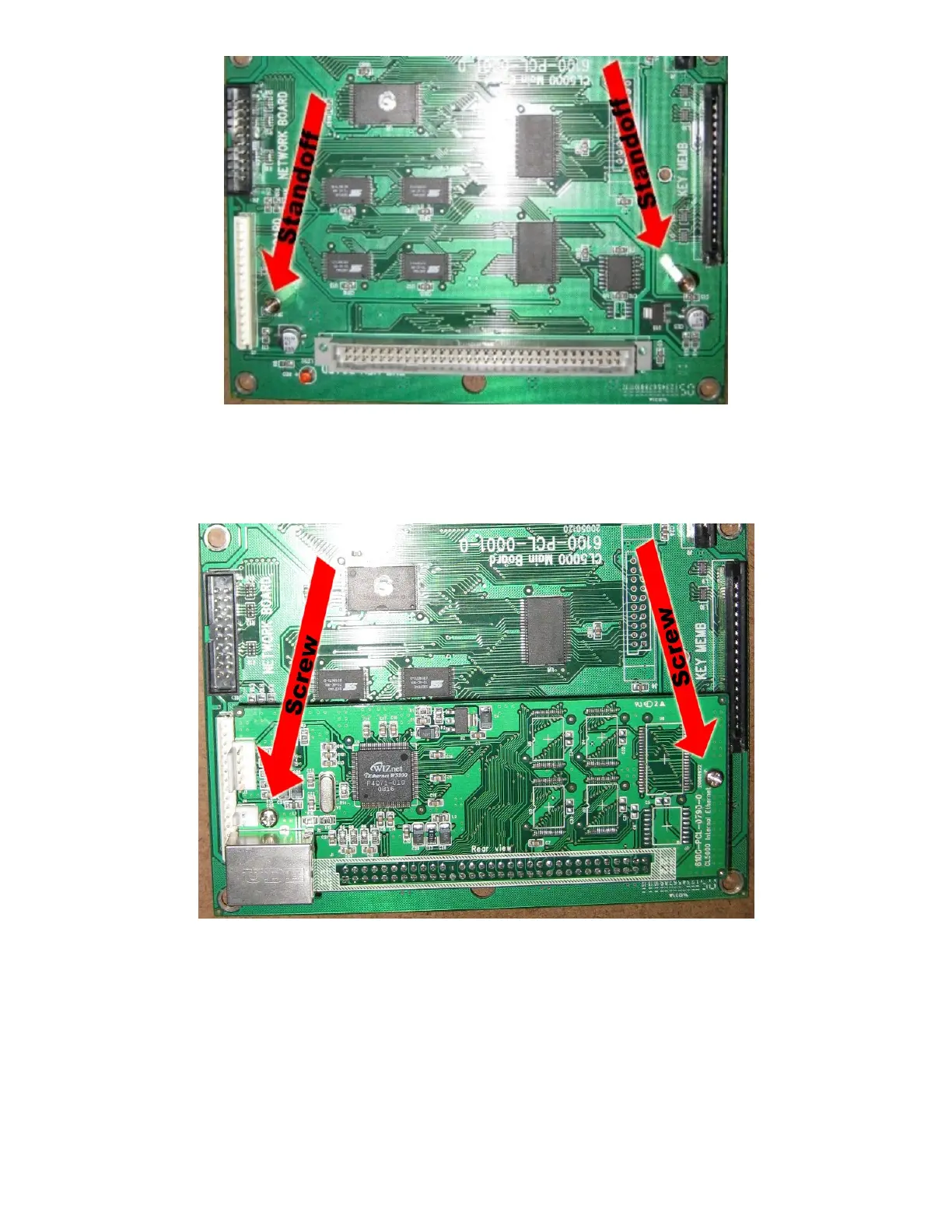
6. If standoffs are not installed on the main board at the locations
indicated by the arrows then remove the main board and install the
standoffs using the nuts and standoffs that are part of the hardware
package.
7. Plug the internal Ethernet board into J3, the grey connector. Secure the
board with two Philips head screws included in the hardware package. If the
main board had to be removed reinstall it now.

 Loading...