Do you have a question about the CAS NC-I and is the answer not in the manual?
Displays all digits on the screen for test mode verification.
Checks Load Cell and A/D Conversion, displays digital value.
Displays IC (CPU) temperature in Celsius.
Displays the current battery value.
Tests Power, Zero, Tare, and Hold keys.
Selects calibration and set mode.
Sets the weight unit (kg, lb, lb<->kg).
Performs zero calibration by detecting zero A/D value.
Sets the minimum division value for weight measurement.
Sets the maximum capacity for weight measurement.
Sets the weight value for span calibration.
Executes the span calibration process.
Configures digital filter for display speed.
Sets the stable time for weight display.
Sets the stable range for weight display.
Controls the backlight behavior.
Configures status display (use or not use).
Sets the hold type (average or peak).
Sets auto display off time.
Overall circuit diagram of the main board.
Circuit diagram for the display unit.
Circuit diagram for the battery charger.
Calibration circuit diagram.
Layout of the main PCB with component placement.
Layout of the display PCB with component placement.
Layout of the charger PCB with component placement.
Pin configurations and function descriptions for the MPU.
Features and block diagram of the operational amplifier.
Electrical limits for safe operation.
DC electrical parameters and specifications.
AC electrical parameters and specifications.
Detailed description of each pin's function.
Indicator initialization failure due to platform shaking.
Initial A/D value out of range on power-on.
Current weight exceeds zero range.
Initial zero A/D value is too high or low.
Span calibration weight exceeds 100% capacity.
Span calibration weight is below 10% capacity.
Initial zero range exceeds 10% of max capacity.
Span calibration weight is 0kg.
Battery needs recharge; power off automatic.
Too heavy object exceeds maximum capacity.
List of parts for the Calibration PCB.
List of parts for the Charger PCB.
List of parts for the Display PCB.
List of parts for the Main PCB.
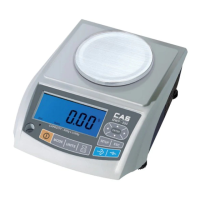
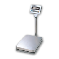
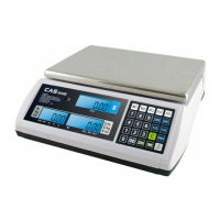
| Display | LCD |
|---|---|
| Auto Power Off | Yes |
| Overload Protection | Yes |
| Platform Size | 230 x 190 mm |
| Weighing Units | g |
| Functions | Hold |