H
halljasonJul 27, 2025
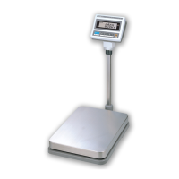
What to do if my CAS AD Scales are not operating (power off)?
- Ssarah17Jul 27, 2025
If your CAS Scales are not turning on, there are several potential causes: * The power ON/OFF key may be damaged, in which case you should check the output voltage while holding the Tact S/W. * The battery may be discharged or not properly connected, so verify the battery connection and voltage. * The fuse may be blown (open), so check the fuse connection. * The power cable could be faulty; in this case, check the output voltage while holding the Tact S/W.