CHAPTER 3
20 Case IH 3230/3240/3320/3330/3340 & 4420/4430/4440, Model Year 2010 & Newer ISO AutoBoom® Installation Manual
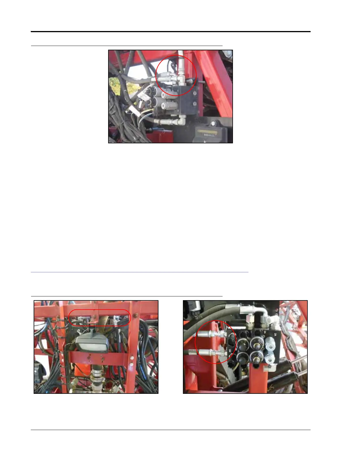
FIGURE 3. Pressure and Tank Hoses Installed
1. Disconnect the machine’s pressure hose from the machine’s hydraulic valve.
2. Install a -8 ORFS M/M/F swivel run tee fitting (P/N 333-0012-028) in the machine’s pressure port.
3. Attach the machine’s pressure hose to the opposite end of the installed tee fitting.
4. Connect the 90° end of the supplied hydraulic hose (P/N 214-1000-311) to the 90° end of the installed tee
fitting.
5. Connect the straight end of the installed hydraulic hose to Port P on the AutoBoom valve.
6. Disconnect the machine’s tank hose from the machine’s hydraulic valve.
7. Install a -8 ORFS M/M/F swivel run tee fitting (P/N 333-0012-028) in the machine’s tank port.
8. Attach the machine’s tank hose to the opposite end of the installed tee fitting.
9. Connect the 90° end of the supplied hydraulic hose (P/N 214-1000-311) to the 90° end of the installed tee
fitting.
10. Connect the straight end of the installed hydraulic hose to Port T on the AutoBoom valve.
INSTALL THE LEFT AND RIGHT CYLINDER HOSES
FIGURE 4. Left and Right Cylinder Hoses Installed
1. Trace the machine’s left and right cylinder tilt hoses from the rod-end of the tilt cylinders to the machine’s
hydraulic valve.