Engine-Engineandcrankcase
Camshaftinstallationandtiming
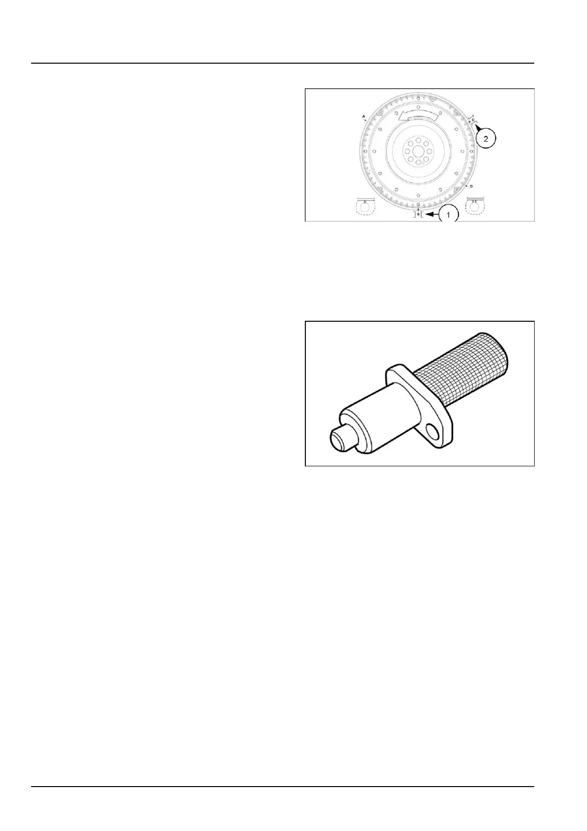
Whentimingoradjustingvalvesitiscriticaltoposition
theA,B,CorDholesinthecenteroftheviewhole(1)at
thebottomofthebellhousing.Seriousenginedamage
canoccurifproceduresarenotfollowedcarefully.
A.TDC3and4
B.TDC1and6
C.TDC2and5
D.54°beforeTDC1and6
Whentimingoradjustingvalvesitiscriticaltopositionthe
A,B,CorDholesinthecenteroftheviewhole(1)atthe
bottomofthebellhousing.Seriousenginedamagecan
occurifproceduresarenotfollowedcarefully.
NOTE:Allreferencestoywheelrotationwillbemadeas
viewedfromtherearoftheengine.
NOTE:TheA,BandCholesaremarkedwithonehash
mark(l)andtheD’holewithtwohashmarks(ll).
RAIL15TR00406FA20
PositiontheywheelatTDC1and6,theBholeatthe
bottom.ThiscanbedonebylocatingtheDholeatthe
bottomviewholeinthebellhousing,andthenturningthe
ywheelcounterclockwiseuntiltheBholeappears.
Oncetheywheelisinthisposition,itshouldbepinned
inpositionwiththeywheelpinningtool380000150inthe
sensorhole.
Theengineisnowreadytohavethecamshaftinstalled.
21
5143149922/02/2018
10.1[10.001]/16