SECTION 00 -- GENERAL INFORMATION -- CHAPTER 1
00-13
8. Attach the PTO assembly to the tractor.
9. Connect the hydraulic hose to the tractor,
preferably to a valve section with a float position.
Select the appropriate port to allow engaging the
float position when lowering.
NOTICE: Check the tractor operator’s manual for
instructions on which outlet should be used for single
acting cylinders.
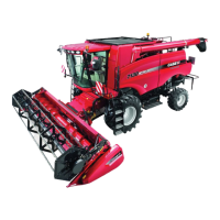
10. Raise the mower with the tractor three-point hitch.
Remove pin, 2, and remove the jack stand, 1.
Attach the jack stand to the mower frame by
sliding the jack stand slots over lugs, 3, on the
frame.
NOTICE: The pin which is attached to the jack stand
with a cable will be installed in the flotation system
later.
11. Level the tractor lower lift links from side to side.
Adjust and lock the sway bars or whatever system
the tractor has to remove as much side
movement as possible.
NOTICE: The tractor lower links should be posi-
tioned straight behind the tractor, or have minimal off-
set. Excessive offset in either direction may cause
damage to the mower PTO drive shaft due to
excessive operating angles or contact with hitch
pins, and will also put “lead” or “lag” into the cutter bar
resulting in reduced cutting width and breakaway
performance.
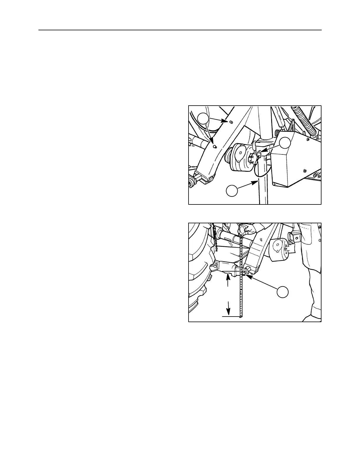
Adjust the limit chain length so the hitch pins, 1,
are as close to (but not less than) 457 mm (18 in)
as possible from the ground when the mower is
supported by the limit chains.
NOTICE: If the high stubble kit is installed on mower,
adjust frame height to 508 mm (20 in) from ground in
order to provide adequate flotation.
A3679-34
1
2
3
22
A3680-12R
1
18 in
(457 mm)
23