SECTION 00 -- GENERAL INFORMATION -- CHAPTER 2
00-7
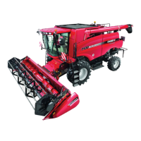
Fully raise the cutter bar to the transport position.
NOTICE: The flotation spring may slightly rub the
canopy support top plate and/or the belt shielding
when the mower is in the transport position.
The hole in the flotation spring rod, 1, should be fully
visible above the upper mount, in order to allow
installation of the flotation engagement pin, 2.
If the hole is not visible, or is partially blocked by the
upper mount, the spring and rod assembly will need
to be lengthened in order to allow engagement of the
flotation system.
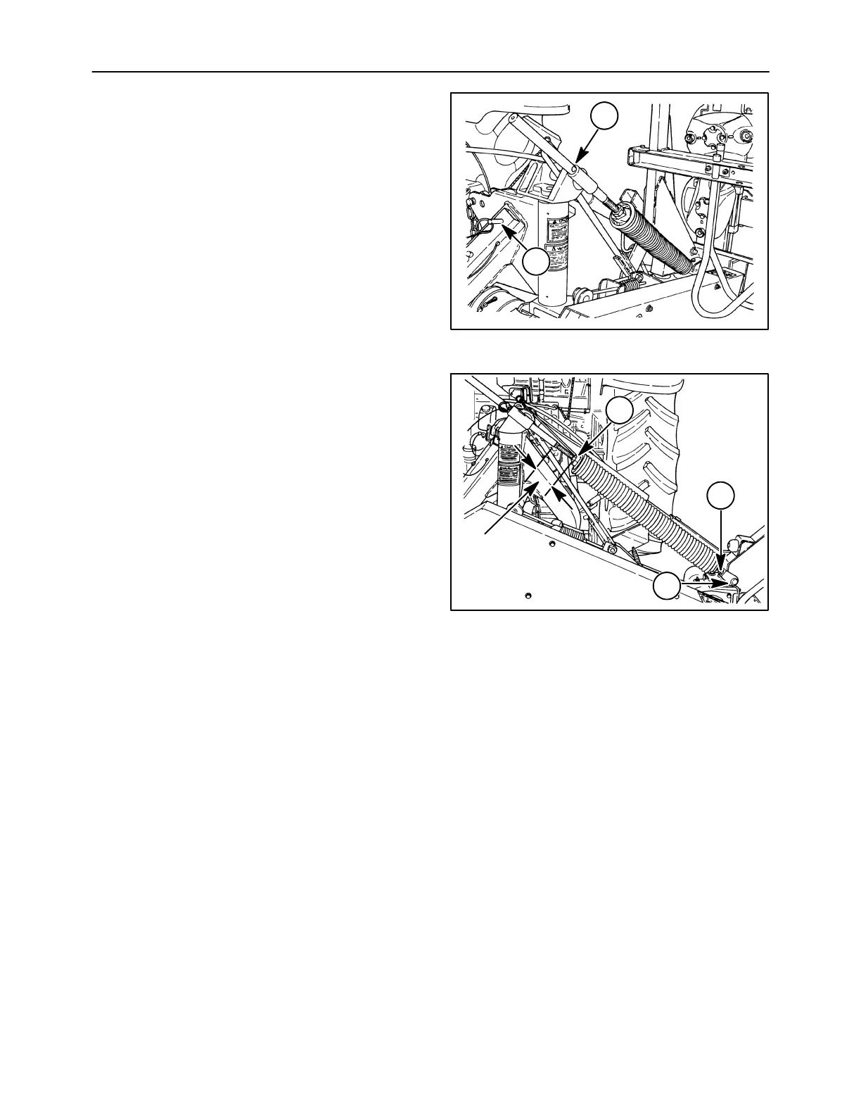
A limited amount of adjustment is available between
the rod and spring assembly. Loosen the jam nut, 1,
and thread the rod out of the spring assembly as
required to allow access to the rod hole when in
transport position. Retighten the jam nut.
NOTICE: Do not thread the rod out more than 114
mm (4-1/2 in) from the spring nut to the shoulder on
rod, or failure of the rod and spring assembly may oc-
cur.
If additional adjustment is required to gain access to
the rod hole to engage the flotation, loosen the jam
nut, 2, between the lower mount rod and the spring
nut, and thread the spring away from the lower
mount. Retighten the jam nut.
NOTICE: Do not thread the lower mount rod out of
the lower mount, 3, or failure of the spring assembly
may occur. Ensure there is a minimum of 5/8 inch
thread engagement in both the lower mount and the
spring assembly, or rod failure will occur.
NOTICE: When completing adjustment, position
flotation spring rod, 1, Figure 41, so that the hole is
slightly above horizontal as viewed from the rear be-
fore tightening the jam nut, as this will ease flotation
pin installation.
Engage the flotation system by inserting the pin
which is wired to the jack stand in the flotation spring
rod hole. The pin has two detent balls and is properly
installed when detents are on either side of the
flotation spring rod.
1
2
36091681
6
2
3
1
114 mm
(4-1/2 in)
A5074-06
7