"'
<
_,
MODEL
12
0
CRAWLER
GENERAL
GENERAL
DESCRIPTION
General Description
The 120
is
a
fully
hydraulic
unit.
Power
for
operation
is
supplied
by
a
Detroit
Diesel 12V-71 engine. Engine
power
is
converted
to
hydraulic energy
by
two
main
pumps and a two-section pump located at the rear
of
the engine.
Hydraulic systems include:
1)
the Main System,
2)
the Pilot System, 3) the Counterweight system, and
4) the
Auxiliary
System.
1)
The Main System powers the
work
functions
(track drive, swing, hoist, crowd and
tool).
Its
pumps
are
driven
off
the engine through a
transmission and clutch which
can
be
either
manually
or
hydraulically disengaged
from
the
engine. The
two
main pumps supply oil
to
two
main control valve banks where
it
is
available
to
operate the individual
work
functions.
LEFT TRACK
TOOL
SWING
2) The
Pilot
System supplies oil
to
the
Modulator
Controls. The Modulator controls replace the
conventional mechanical linkage
to
the main
valves
and provide precise hydraulic
control
of
the main valve spools. The
pilot
system also
supplies oil
for
release
of
the digging and house
brakes,
for
release
of
the hoist and
crowd
anti-
drift
valves,
and
for
clutch engagement
or
dis-
engagement.
3) The Counterweight System allows the 14
ton
counterweight
to
be
easily removed
or
installed.
4) The
Auxiliary
System
is
connected directly
into
the
pilot
system. Its pump
is
driven
by
an
electric motor, independent
of
the engine, and
can
be
used
in
case
of
engine failure
to
pressurize the
pilot
system.
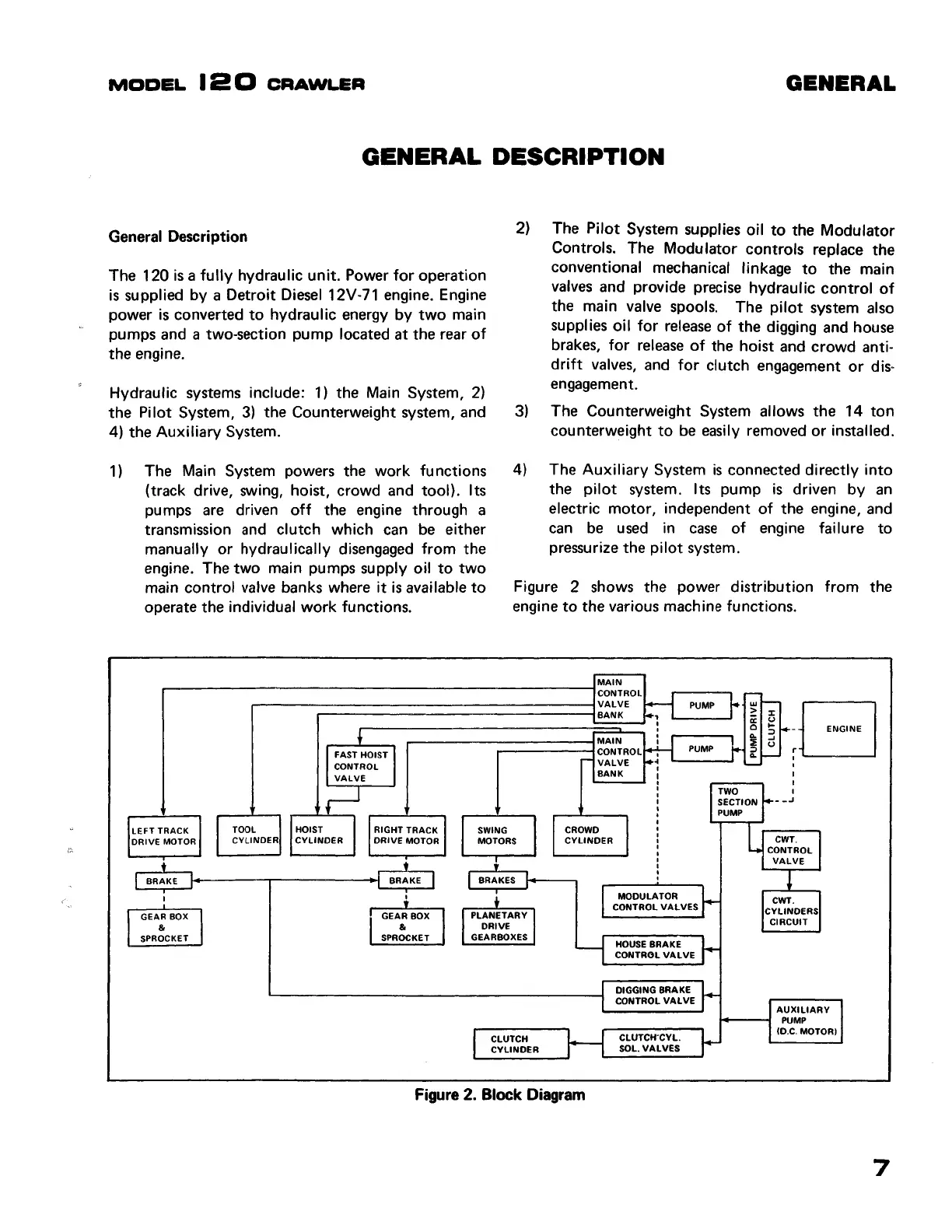
Figure 2 shows the power distribution
from
the
engine
to
the various machine functions.
MAIN
CONTROL
VALVE
PUMP
BANK
MAIN
CONTROL
PUMP
VALVE
:G
I
BANK
__
.,
CROWD
DRIVE
MOTOR
CYLINDER
MOTORS
CYLINDER
CWT.
BRAKE
GEAR
BOX
&
SPROCKET
BRAKE
GEARBOX
&
SPROCKET
PLANETARY
DRIVE
GEARBOXES
CLUTCH
CYLINDER
Figure
2.
Block
Diagram
MODULATOR
CONTROL VALVES
HOUSE
BRAKE
CONTROL VALVE
DIGGING
BRAKE
CONTROL VALVE
CLUTCH"CYL.
SOL. VALVES
CONTROL
VALVE
CWT.
CYLINDERS
CIRCUIT
AUXILIARY
i-----1
PUMP
(l).C. MOTOR)
7
Find manuals at https://best-manuals.com
 Loading...