INTRODUCTION
Installationofangeconnectors
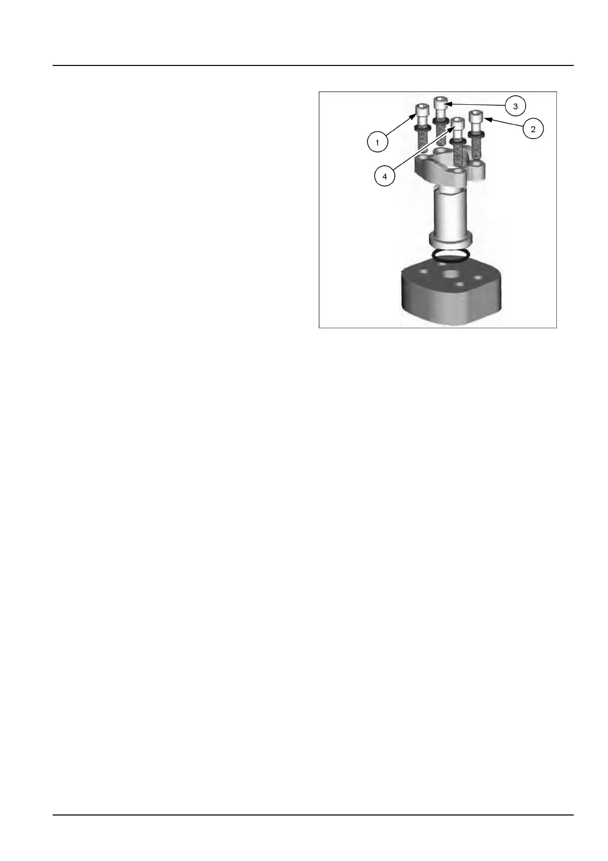
Flangeconnectionstypicallyhavefourbolts,although
someangeconnectionsmayhavemoreorfewer.The
angeconnectorconsistsoffourmaincomponents:
•
Abody(angehead)
•
AnO-ring
•
One“captive”ortwo“split”angeclamps
•
Boltsandwashers
1.Removeprotectiveconnectorcapsonlyimmediately
priortoassembly.
2.Inspectthecomponentstoensurethatthemaleand
femaleportthreadsandsealingsurfacesarefreeof
burrs,nicks,andscratches,oranyforeignmaterial.
Donotuseifimpuritiesarefound.
3.PlacetheO-ringinthegroove,thegroovewillbe
eitherontheportsideortheangeside.
4.Assembletheangeheadandtheclamps.
5.Positionandholdtheangeassemblyovertheport.
6.Fingertightenthebolthardwareevenlyandina
crossingpattern.
7.Tightenthebolthardwareto60%ofthetorquevalue.
Usethesamecrossingpattern.Seethetorquetables
forthepropertorquevalue.
NOTE:ForbolthardwarethatisnotMetricClass8.8
and10.9orInchGrade8seethe“Torque-Minimum
tighteningtorquesfornormalassembly”Torque-
Minimumtighteningtorquesfornormalassembly
().
8.Tightenthebolthardware1and2to100%ofthe
torquevalue.
9.Tightenthebolthardware3and4to100%ofthe
torquevalue.
RAIL15TLB0611BA4
4804856726/04/2017
27