Engine-Engineandcrankcase
19.Fixtheendoftheexhaustsystempipe(1)totheen-
ginewithanewclamp(2).Tightentheclampto5.7–
6.3N·m(4.2–4.6lbft).
LEIL17WHL0054AB17
20.Installthealarmback-up(1)totherearmufersupport
withfourbolts,washers(underboltheadandnut)and
nuts.ConnectwireO_JBofconnectorBU1to“NEG”
and35AofconnectorBU2to“H1”(2)ofalarmback-
up.Securethewiretotherearmufersupportwith
cableties.
21.Installthefuelpre-ltersupportbracket(3)totherear
mufersupportwithtwobolts,washers(underbolt
headandnut)andnuts.
22.Installthefuelpre-lter(4)tothesupportbracketwith
twobolts,washers(underboltheadandnut)andnuts.
AtthistimeconnecttheGRD_WIFwire(5)byusing
thesamehardware.
23.ConnecttheWIFconnector(9)andWSHconnector
(6)tothefuelpre-lter.
24.Usetheclamp(7)tosecurethefueltanksuctionhose
totherearmufersupport.
25.Connectthefuelpre-ltertoenginehose(8)tothe
engine.
LEIL17WHL0055AB18
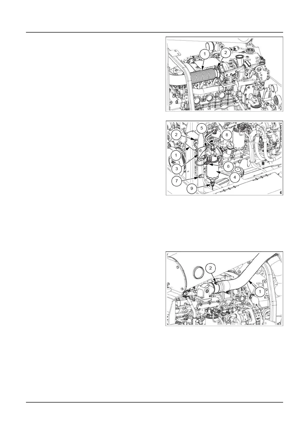
26.Installtheairintakecoolingline(1)withclamps.
Torquetheclamps(2)attheendsmatingthecharge
aircoolerandengineto10.1–11.3N·m(7.4–8.3lb
ft).
NOTE:ensureclearanceof16.5–26.5mmbetweenthe
chargeairintaketubeandthemufer.
LEIL17WHL0090AB19
48083741_EN31/07/2018
10.1[10.001]/23