6 SECTION 39 - CHASSIS
2.2 COMPONENTS BELOW THE CHASSIS
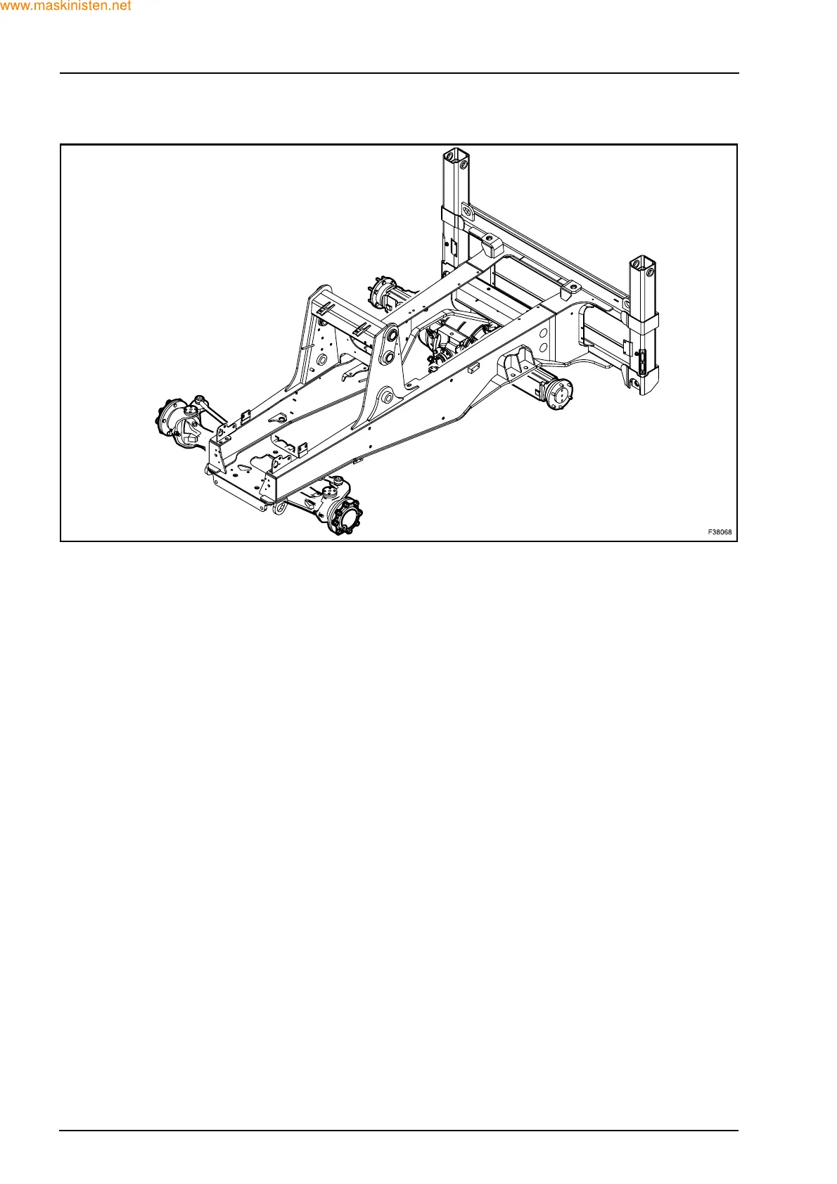
FRONT AXLE
The front axle is attached to the underside of the
chassis by 6 through screws (2WS) or 4 through
screws (4WS).
To remove front axle from the machine:
Z Park the machine on a level ground.
Z Stop the engine, remove the key and relieve any
residual pressure in the backhoe and loader at-
tachment systems by moving the loader and back-
hoe attachment control levers through all operating
position.
Z Lower the stabilizers to the ground.
Z Lower the loader bucket on the ground.
Z Using the loader bucket raise the front of the ma-
chine, high enough to remove the front wheels.
Z Place stands under the chassis, supporting appro-
priately the machine.
Place under the axle the appropriate supporting/
removing tool.
Z Remove the nuts on the wheels and then remove
them.
Z Disconnect the steering cylinder hoses.
Z Remove the axle swivel pin attaching bolts (4WD).
Z Disconnect the spider coupling (4WD).
Z Remove the axle bolts.
Z Remove the front axle.
REAR AXLE
The rear axle is attached to the frame at the rear of
the machine by 4 through bolts.
To remove rear axle from the machine:
Z Park the machine on a level ground.
Stop the engine, remove the key and relieve any
residual pressure in the backhoe and loader at-
tachment systems by moving the loader and back-
hoe attachment control levers through all operating
position.
Z Lower the stabilizers to the ground.
Z Lower the loader bucket on the ground.
Z Using the stabilizers, raise the rear of the machine,
high enough to remove the rear wheels.
Z Place stands under the chassis, supporting appro-
priately the machine.
Z Remove the nuts on the wheels and then remove
them.
Z Disconnect the steering cylinder hoses (4WS).
Z Disconnect the brake system hoses.
Z Disconnect the connector of harness of the differ-
ential lock (electrically controlled version).
Z Remove axle swivel pin attaching bolts.
Z Disconnect spider coupling.
Z Remove the axle bolts.
Z Remove the rear axle.