50 SECTION 50 - CAB HEATING AND AIR CONDITIONING
LOW PRESSURE CUT-OUT SWITCH
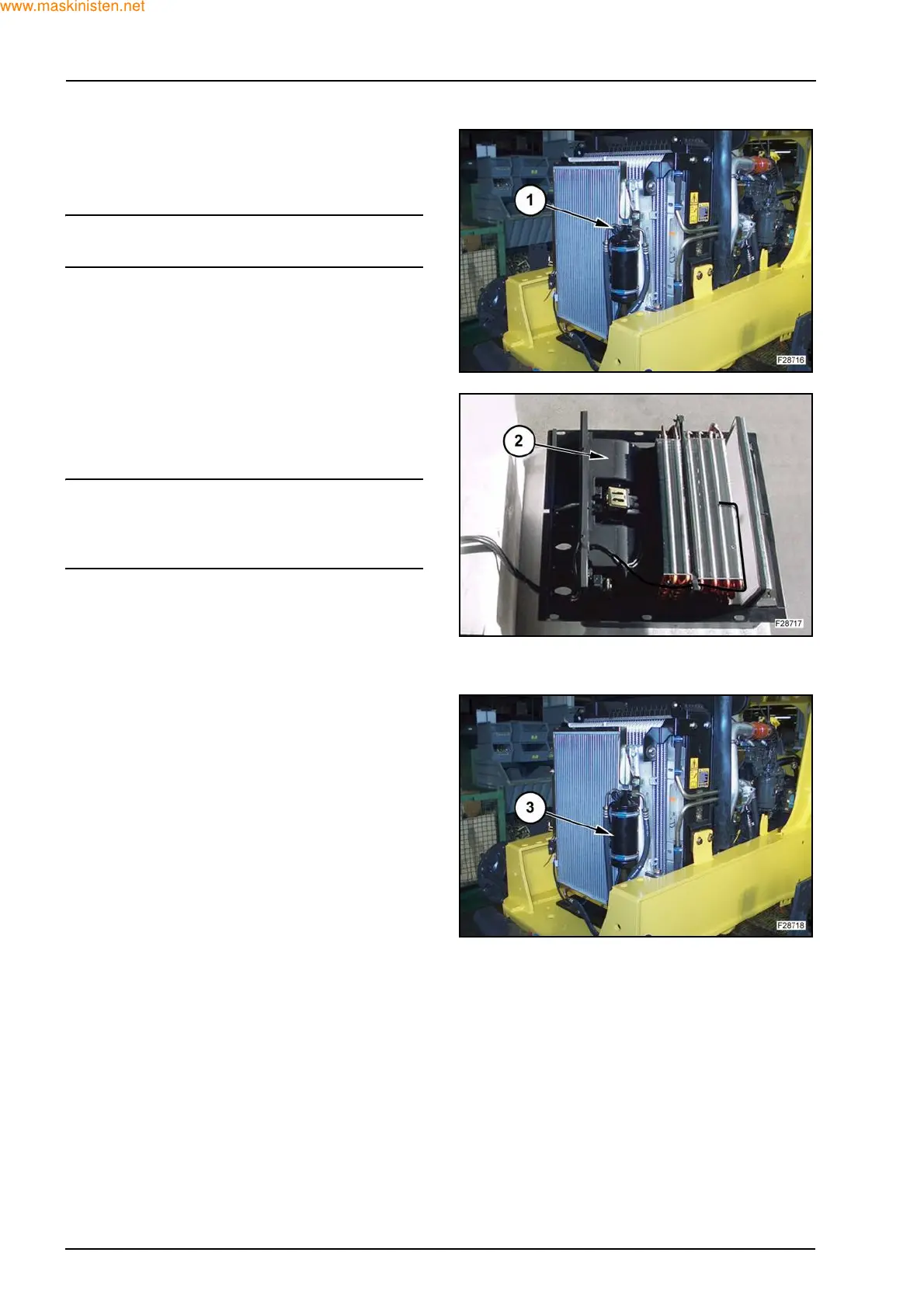
1. With the engine OFF check continuity across the
switch contacts. If the switch (1) indicates an
open circuit, replace it as described below.
IMPORTANT: the pressure switch can not be re-
placed without discharging the system.
2. Remove switch by unscrewing from self sealing
Schrader valve.
3. Replace with new switch and connect to har-
ness.
BLOWER MOTOR ASSEMBLY
If necessary, the blower motor can be removed with-
out discharging the system as follows:
1. Remove the cab seat mounting plate.
NOTE: take care not to damage hoses during this
operation. If the cab heater hoses restrict movement
of the housing drain the heater assembly and dis-
connect the hoses.
2. Disconnect the motor wiring connector block.
3. Remove the remaining motor securing screws
and withdraw motor.
4. Re-assembly follows the disassembly procedure
in reverse.
RECEIVER DRYER
The receiver/dryer (3) cannot be overhauled and
must be replaced as an assembly. The receiver/dry-
er assembly should be replaced if it is suspected that
moisture is in the system.
The receiver dryer must also be replaced if the sys-
tem has been discharged and the air conditioning
joints disconnected.
1. Discharge and reclaim refrigerant gas using cer-
tified recovery systems.
2. Disconnect the hoses and switch and remove
the dryer from the loader backhoe.
3. Drain the refrigerant oil from the receiver dryer
into a clean calibrated container. Measure the
quantity of oil obtained and add the same quan-
tity of new refrigerant oil directly into the new
item.
4. Cap and plug all fittings to prevent any dirt enter-
ing the system.
5. Install a new receiver dryer.