2000-10
Installation
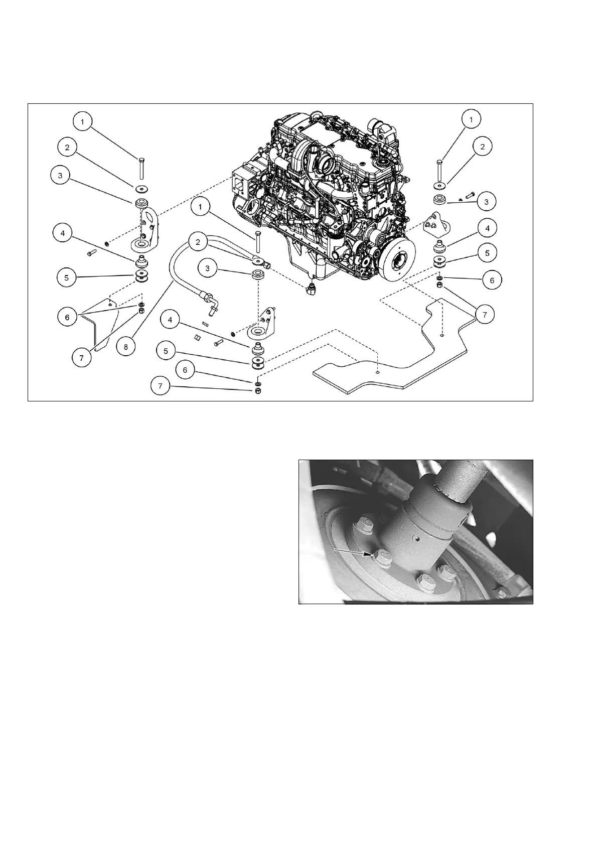
W130R0032
STEP 42
If engine rubber isolators require replacement,
remove and discard isolators (3 and 4). Install new
rubber isolator (4), then rubber isolator (3).
STEP 43
Slowly raise engine and move into position over rear
chassis. Be sure all harness connections and hoses
are out of the way then lower engine. Put washer (5)
between front rubber isolator (4) and chassis. Install
washer (2), bolt (1), washer (6), and nut (7) in engine
isolators. Lower engine into position.
STEP 44
Tighten engine mounting bolts to a torque of 244 to
298 Nm (180 to 220 lb-ft).
STEP 45
Disconnect lifting equipment from engine lifting
brackets.
STEP 46
Connect engine oil drain hose to frame bracket.
STEP 47
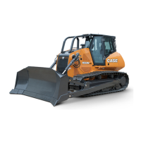
BD03A172
At front of engine, position drive shaft on engine
coupling. Install six bolts to secure drive shaft to
engine coupling. Tighten the six bolts to a torque of
53 to 62 Nm (39 to 46 lb-ft).
1. ENGINE MOUNT BOLT 3. INSOLATOR UPPER 5. WASHER 7. NUT
2. WASHER 4. INSOLATOR LOWER 6. WASHER 8. REMOTE OIL DRAIN HOSE