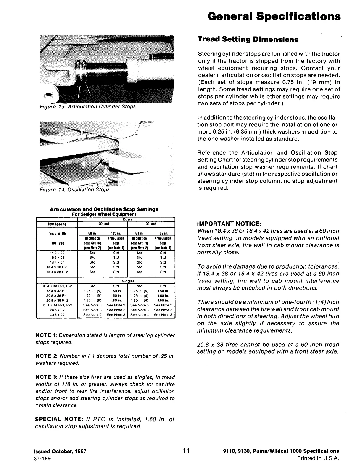
Figure 13: Articulation Cylinder Stops
r:·-=
I
/~=-~·····~--~/!.
Figure
Articulation and Oaclllatlon Stop Setting•
For Steiger Wheel Equipment
Dual•
Row Spacing 30 Inch 32 inch
Tmd Width
60 In.
120 In. 64 In. 128 In.
01clll1llon Articulation 01clll1llon Artlculallon
Tire Type
Stop Setting
Stop
Stop Setting Stop
(HI Nole 21 (HI Note 11
(111 Note 2)
(mNote 11
14.9 X 38 Std Std Std Std
16.9
X 38
Std
Std Std Std
18.4
X 34 Std Std
Std Std
18.4 x 38 A-1 Std Std Std Std
18.4 x 38 R-2 Std Std Std Std
Single•
18.4 x 38 A-1. A-2 Std
Std Std Std
18.4 x 42 A-1
1.25 in (5)
1.50 in 1.25 in. (5) 1.50 in.
20.8
x 38 A-1 1.25 in. (5) 1.50 in 1.25 in. (5)
1.50 in.
20.8
x 38 A-2
1.50
In. (6)
1.50
in 1.50 in. (6) 1.50 in.
23.1 x 34 A-1. A-2 See Note 3
See Note 3 See Note 3 See Note 3
24.5
X 32 See Note 3 See Note 3 See Note 3 See Note 3
30.5
X 32
See Note 3 See Note 3 See Note 3 See Note 3
NOTE 1: Dimension stated is length of steering cylinder
stops required.
NOTE 2: Number in ( ) denotes total number of .25 in.
washers required.
NOTE 3:
If these size tires are used as singles, in tread
widths of 118 in. or greater, always check for cab/tire
and/or front to rear tire interference, aajust ocillation
stops and/or add steering cylinder stops as required to
obtain clearance.
SPECIAL NOTE: If PTO is installed, 1.50 in. of
oscillation stop adjustment is required.
Issued October, 1987
37-189
11
General Specifications
Tread Setting Dimensions
Steering cylinder stops are furnished with the tractor
only if the tractor is shipped from the factory with
wheel equipment requiring stops. Contact your
dealer if articulation or oscillation stops are needed.
(Each set of stops measure 0.75 in. (19 mm) in
length. Some tread settings may require one set of
stops per cylinder while other settings may require
two sets of stops per cylinder.)
In addition to the steering cylinder stops, the oscilla-
tion stop bolt may require the installation of one or
more 0.25 in. (6.35 mm) thick washers in addition to
the one washer installed as standard.
Reference the Articulation and Oscillation Stop
Setting Chart for steering cylinder stop requirements
and oscillation stop washer requirements. If chart
shows standard (std) in the respective oscillation or
steering cylinder stop column, no stop adjustment
is required.
IMPORTANT NOTICE:
When 18.4 x 38 or 18.4 x 42 tires are used at a 60 inch
tread setting on models equipped with an optional
front steer axle, tire wall to cab mount clearance is
normally close.
To avoid tire damage due to production tolerances,
if 18.4 x 38 or 18.4 x 42 tires are used at a 60 inch
tread setting, tire wall to cab mount interference
must always be checked in both directions.
There should be a minimum of one-fourth (1 /4) inch
clearance between the tire wall and front cab mount
in both directions of steering. Adjust the wheel hub
on the axle slightly if necessary to assure the
minimum clearance requirements.
20.8 x 38 tires cannot be used at a 60 inch tread
setting on models equipped with a front steer axle.
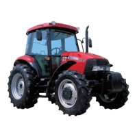
9110, 9130, Puma/Wildcat 1000 Specifications
Printed in U.S.A.
 Loading...