HYDRAULICS – CX210/CX240
6 - 26
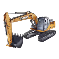
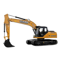
CX EXCAVATORS
ATTACHMENT
Boom Lower
1) When a built-in anti-drift valve in the control valve is released and boom1 control spool is
shifted, the boom can be lowered.
2) A regeneration valve inside the boom1 control spool provides additional speed.
3) Only one pump flow is used.
Oil flow from pump2 (rear pump) enters the P2 port of the control valve. When the boom
hand control is operated for boom down pilot pressure is directed through the cushion valve
to the boom1 control spool of the main control valve. Pilot pressure is also sent to the boom
down anti-drift valve. When the anti-drift valve and boom1 control spool is shifted boom down
is achieved.
When the boom is raised the spring chamber of the anti-drift valve is “charged” with boom up
pressure. This is done through a pilot signal from the cylinder circuit, which passes through
the anti-drift pilot valve to the spring chamber of the anti-drift valve. With equal pressure on
each side of the valve the spring is able to hold the valve closed. This keeps boom drift
through the control spool at a minimum. When lowering the boom a pilot signal from the
boom control pilot circuit is also routed to the anti-drift pilot valve. The valve is shifted and
allows the “charged” oil in the spring chamber to exit to the return circuit. Now the anti-drift
valve will open and boom lowering is activated.
The cylinder return passes through an orifice in the main control spool. This creates
backpressure in the circuit. There is a check valve in the spool between the return and supply
circuit. If the supply pressure fall below the backpressure in the cylinder return circuit oil can
flow to the supply side through the check valve. This protects from cavitation and helps with
boom lowering speed.
Whenever the boom is lowered part of the pump supply is allowed to bleed off through the
open center circuit through an orifice. This is to turn the pump “0N” more slowly and maintain
some negative control pressure to the pump to limit its output. This is to prevent the pressure
spike that occurs when the boom starts to lower.