ELECTRIC CIRCUIT
5 - 20
CASE TRAINING CENTER
AUGUST 2000
Hammer mode control
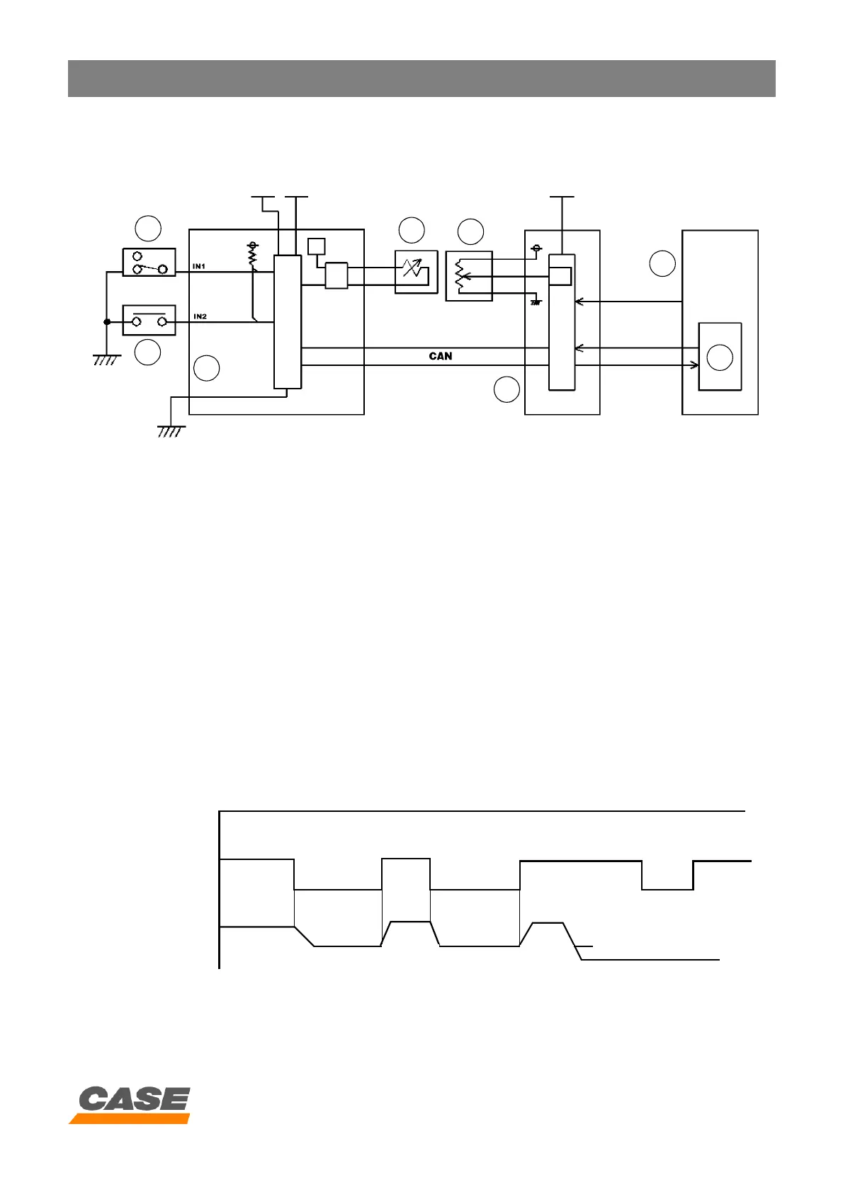
1) Circuit configuration
CS00F513
1. Hammer/grab switch
2. Hammer pilot switch
3. Main electronic control box
4. Proportioning valve
5. Throttle control
6. Engine electronic control box
7. Electronic acceleration
8. Electronic acceleration
2) Operation
When the hammer/grab switch (1) is turned to hammer function (when the hammer/grab option is installed) and
the option pedal is pressed, the hammer pressure switch (2) is on and the engine speed drops to the pre-set
hammer speed (see engine speed setting for hammer option).
When the option pedal returns to the neutral position, the hammer pressure switch (2) is deactivated and the
engine speed returns to the throttle control setting.
For the pre-set hammer engine speed to function, the throttle control (5) has to be set at a higher speed than the
pre-set hammer engine speed.
When the hammer pressure switch (2) is on, the value of current delivered by the proportioning valve (4) becomes
that of mode "S".
3) Time diagram
1
2
3
4
5
6
7
8
Pre-set hammer speed
(5V)
(0V)
(5V)
(0V)
Engine speed
Hammer/grab
switch
Hammer pilot
pressure
switch
Throttle control lower than
pre-set hammer speed