5 - 29
ELECTRIC CIRCUIT
CASE TRAINING CENTER
AUGUST 2000
Engine emergency stop
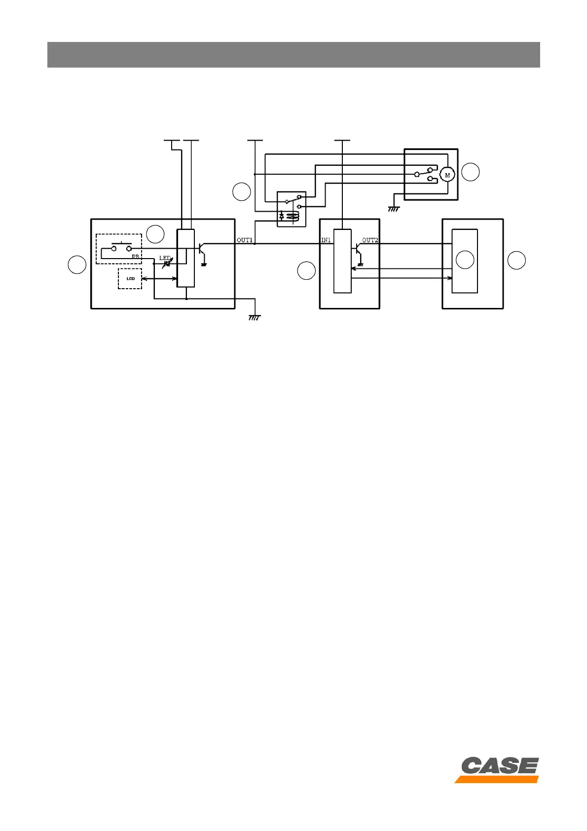
1) Circuit configuration
CS00F517
1. Instrument panel
2. Engine emergency stop switch
3. Engine emergency stop relay
4. Engine electronic control box
5. Emergency stop motor
6. Engine
7. Electronic acceleration
2) Operation
1. If the emergency stop switch (2) is pressed, the transistor output OUT 1 = 0 volt and the LED on the switch
flash.
2. Since OUT 1 is at 0 volt, the emergency stop relay (3) is activated, along with the emergency stop motor (5).
3. The stop signal input (IN1) on the engine electronic control box (4) falls to 0 volt, the engine electronic control box
(4) accepts that as the emergency stop status and transmits the "stop engine" signal OUT 2 = 0 volt.
4. The electronic acceleration starts to control the engine shut down when it received the signal (position of the rack =
0 mm).
5. The emergency stop status is maintained even after the ignition switch is turned off. To deactivate the emergency
stop, the emergency stop switch has to be pressed again, with the LED off.
1
2
3
4
5
7
6