HYDRAULIC PRESSURE SETTINGS
7 - 9
CASE TRAINING CENTER
AUGUST 2000
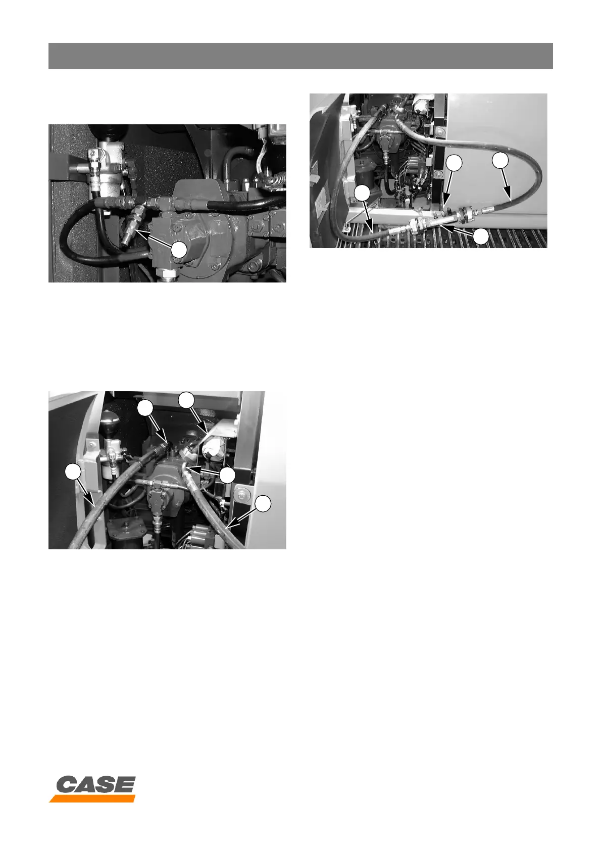
2. Installing the pilot pressure test
point
CD00E191
Install a pressure test point (P3) on the pilot circuit
using the T-union and quick coupling supplied in the kit
CAS 30038.
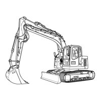
3. Installing the flowmeter
(Checking hydraulic pump flows)
CX130
CD00F008
Remove the hose (1) de the pump outlet to be
checked.
Install the flange (2) (CAS 2764) on the hose (1).
Connect the elbow union (3) (CAS 2764) on the pump
outlet to be checked.
Install the hoses (4) (CAS 30036) on the elbow union
(3) and on the flange (2).
CX130
CD00F007
Install the flowmeter (5) on the hoses (4).
Fasten the flowmeter to the upperstructure.
Connect the multi-handy 2051 connecting cable to the
plug on the flowmeter detector (6).
P3
4
2
1
3
4
5
4
6
4