— 11 —
Connector (CN16)
Connector (CN17)
Power switch
Connector (CN18)
Connector (CN20)
Connector (CN19)
Connector (CN3)
Connector (CN2)
Connector (CN1)
Connector (CN4)
Connector (CN1)
Connector (CN2)
Connector (CN3)
Connector (CN8)
Connector (CN12)
Connector (CN13)
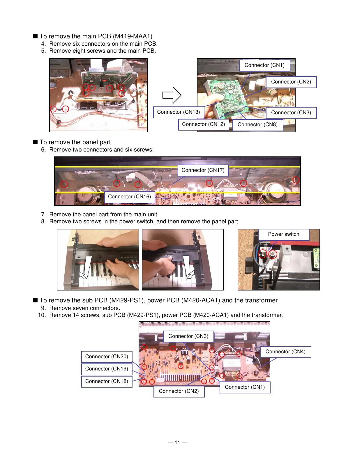
■ To remove the main PCB (M419-MAA1)
4. Remove six connectors on the main PCB.
5. Remove eight screws and the main PCB.
■ To remove the panel part
6. Remove two connectors and six screws.
■ To remove the sub PCB (M429-PS1), power PCB (M420-ACA1) and the transformer
9. Remove seven connectors.
10. Remove 14 screws, sub PCB (M429-PS1), power PCB (M420-ACA1) and the transformer.
7. Remove the panel part from the main unit.
8. Remove two screws in the power switch, and then remove the panel part.