- 7 -
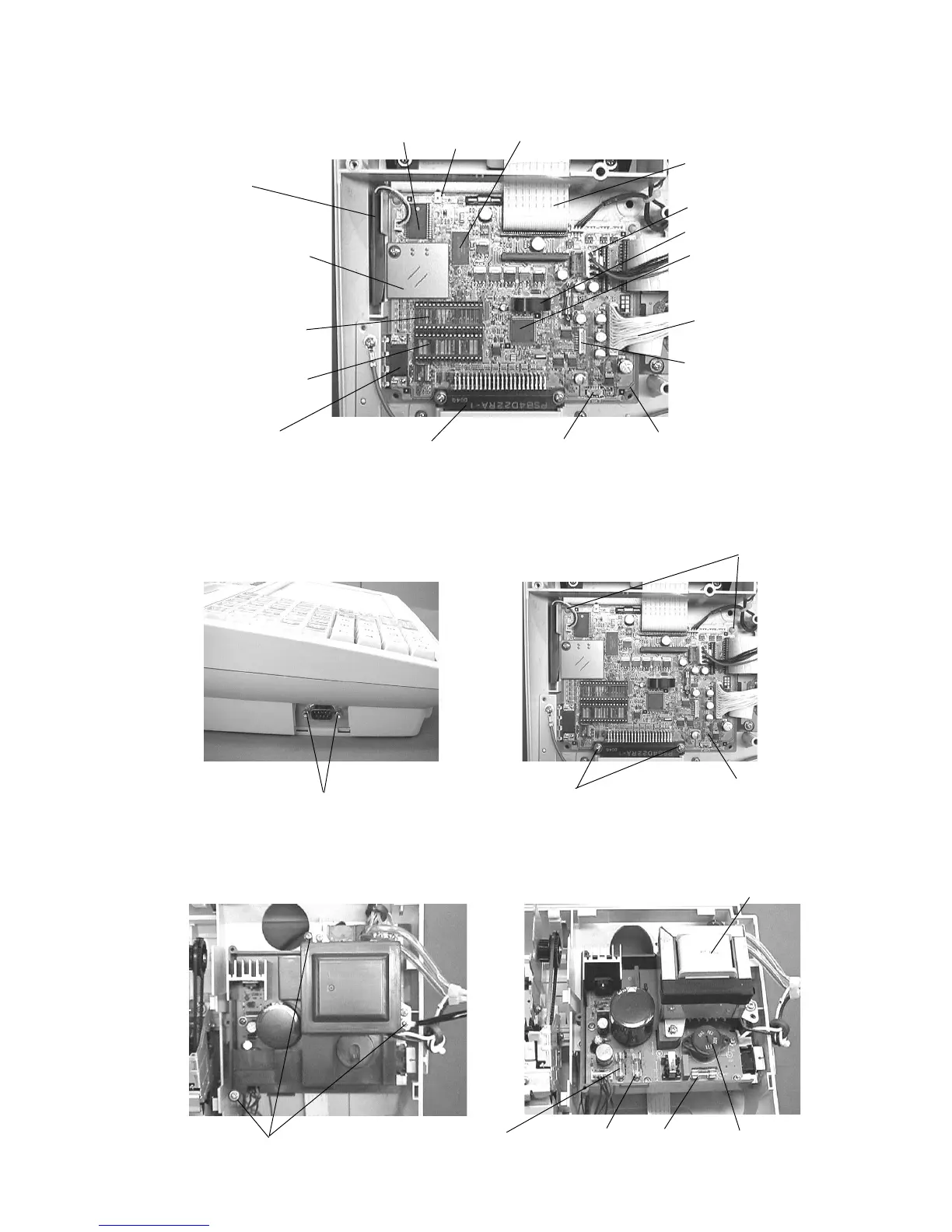
6. To remove the Main PCB, release the 2 screws of point A and 2 locking supporters of point B
and the COM1 port outside screws.
5. The each parts of the Main PCB are located as shown in the picture.
Note: RAM2 is not used for CE-6000.
7. Power supply unit cover is removed by 3 screws. And, the 3 Fuses are located as shown in the
picture.
Battery
Flash ROM 1 (2 Mbytes)
Main PCB
Flash pack connector
(Not used for CE-6000)
RAM 1 (128 Kbytes)
Flash ROM 2
(Not used for CE-6000)
RAM 4
(Not used for CE-6000)
RAM 3
(Not used for CE-6000)
COM 1 port
CPU
Buzzer
Printer cable
Display cable
Power supply connector
Reset Switch
Keyboard select switch
(Not used for CE-6000)
Clerk key connector
(Not used for CE-6000)
Remove 2 screws for COM 1 port.
Point A
Remove 2 screws.
Point A
Remove 2 screws.
Main PCB
Remove the 3 screws.
Then, remove the power supply cover.
Power transformer
Voltage selector
(Not used for CE-6000)
Fuse F1
250V 1A
Fuse F2
250V 2A
Fuse F3
250V 400mA
(Not used for CE-6000)