CTK-4200
– 13 –
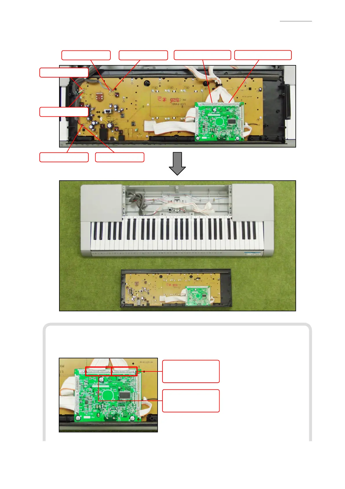
A-4. Unsolder six lead wires and two FFCs.
A-5. Remove the main panel unit.
FFC (M802-KYA1) FFC (M802-KYA2)
Lead wire (Black)
Lead wire (Green)
Lead wire (Red)
Lead wire (Brown)Lead wire (Blue)
Lead wire (White)
<Notes On Assembly>
• The number of pins on the PCB pad differs from that on the cable. Solder in the way that No.1
pin on the cable (orange) is connected to No.1 pad on the PCB.
FFC (M802-KYA2)
PCB: 15 pads
Cable: 11 pins
FFC (M802-KYA1)
PCB: 16 pads
Cable: 13 pins
 Loading...