— 9 —
3) Equipment connection/Procedure
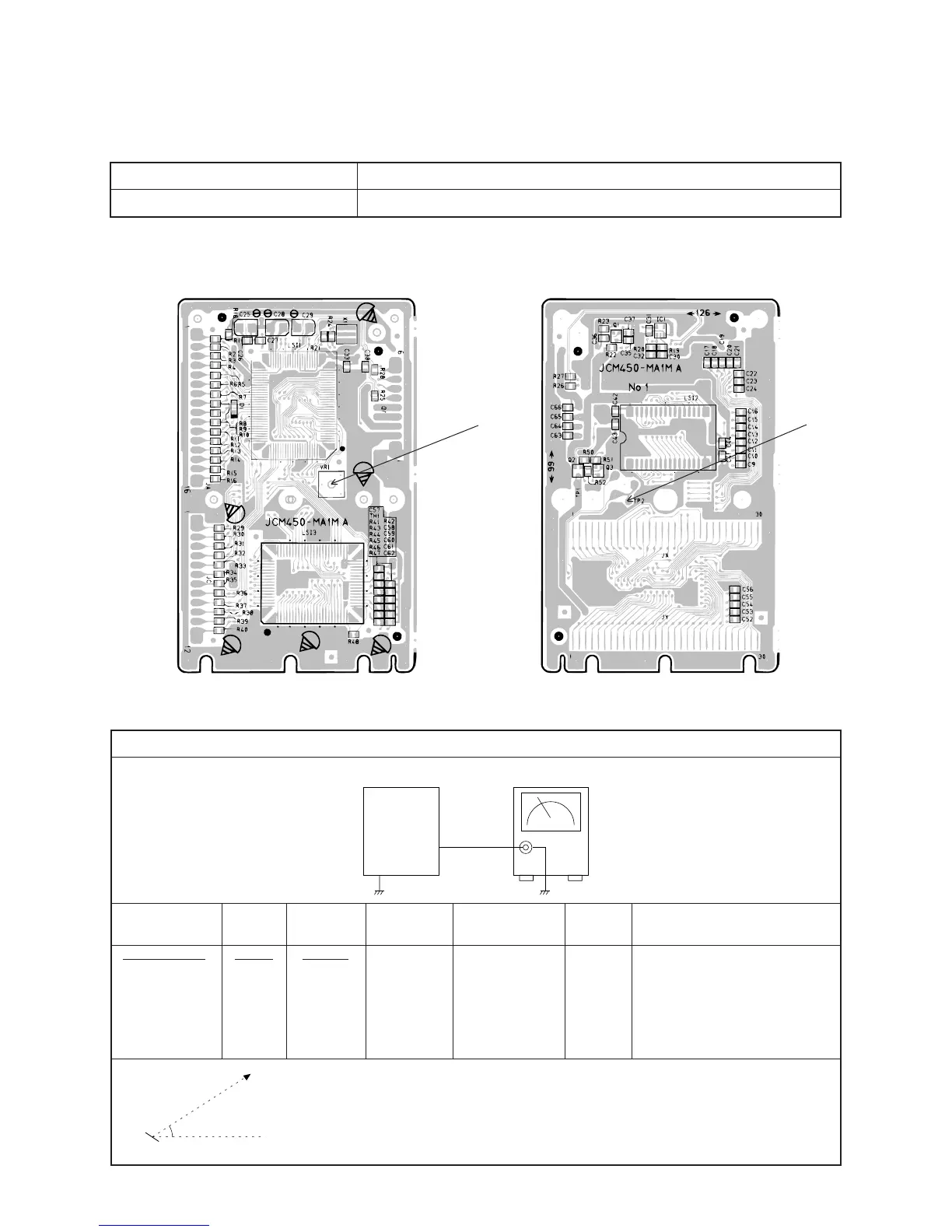
ADJUSTMENT
MAIN PCB
1) Items to be adjusted:
2) Adjustment and Test Point Locations
Item
Measuring Instrument
Vop voltage setting Voltmeter
TP2
(Top View) (Bottom View)
VR1
Vop voltage setting
Watching the LCD at a 41.20° angle to the horizontal, adjust Vop
voltage so that unenergized segments are seen dimly.
Output
Set Voltmeter
TP2
41.20°
LCD
Eye
Input
Connection
Input
Point
Input
Signal
Adjust
Output
Connection
Output
Point
Adjust for
VR1 Voltmeter TP2
Adjust for 4.2 ~ 4.3 V reading
on voltmeter under the tem-
perature 20 ~ 25 °C.
Make fine adjustment accord-
ing to the following instruc-
tion.
 Loading...