— 6 —
emaNegatloVfonoitareporoF
DDVV5+
,MARtceffE,MARegarotsgnikroW,MORecruosdnuoS,PSD,CIteseR,UPC
revirdDEL
DDVDV5+UPCkcajIDIM,kcajniatsuS,
DDVAV5+retliF,CAD
DDVLV5+AG
CCVV9+reifilpmarewoP
CCLVV2+pmaltoliP
DDCLV6.5+revirdDCL
POWER SUPPLY CIRCUIT
The power supply circuit generates seven voltages as shown in the following table. VDD voltage is always
generated. The others are controlled by APO signal from the CPU.
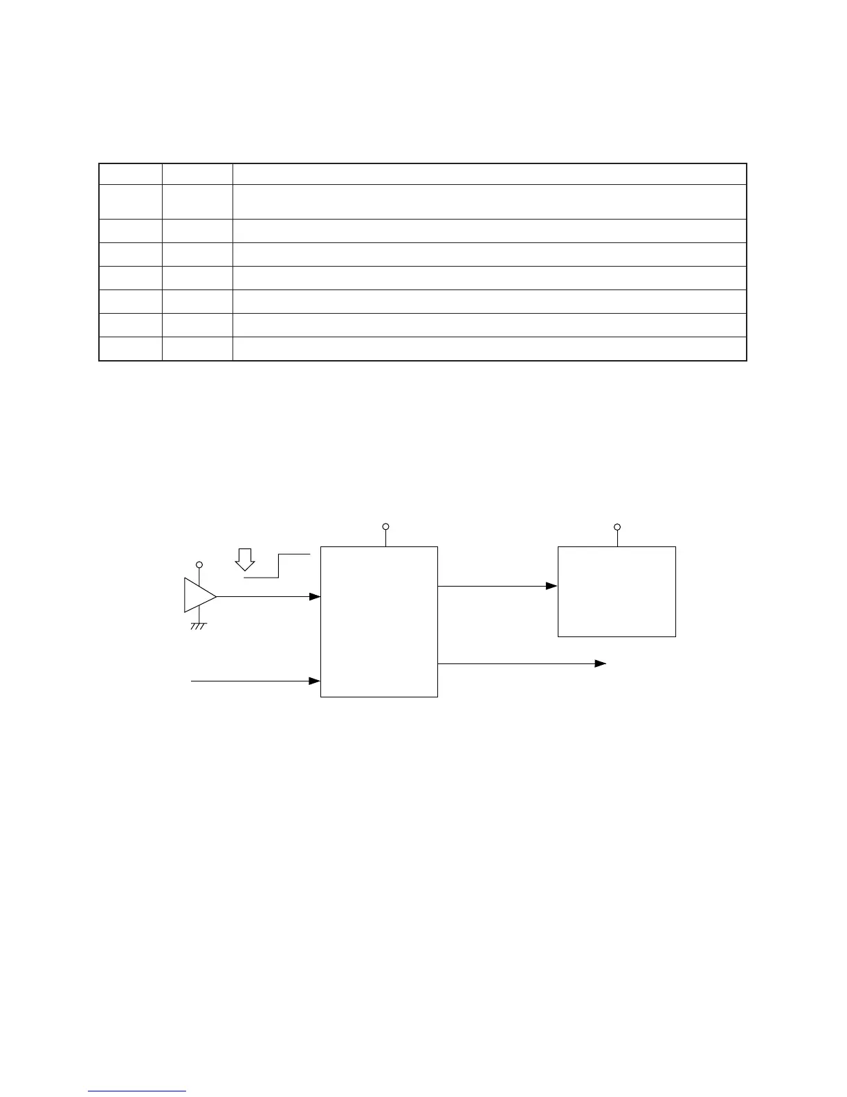
RESET CIRCUIT
When batteries are set or an AC adapter is connected, the reset IC provides a low pulse to the CPU. The
CPU then initializes its internal circuit, and clears the working storage RAM.
When the power switch is pressed, the CPU receives a low pulse of POWER signal. The CPU sends APO
signal to the power supply circuit, also sends a reset signal to the DSP.
Reset IC
IC1
RN5VD40AA
DSP
LSI2
HG51B277FB-1
VDD
Reset signal
To power supply circuit
VDD
Battery set
RESET
VDD
POWER
From power switch
NMI
RSTB
RESB
APO
PLE
CPU
LSI1
GT913F
SCK0
 Loading...