– 8 –
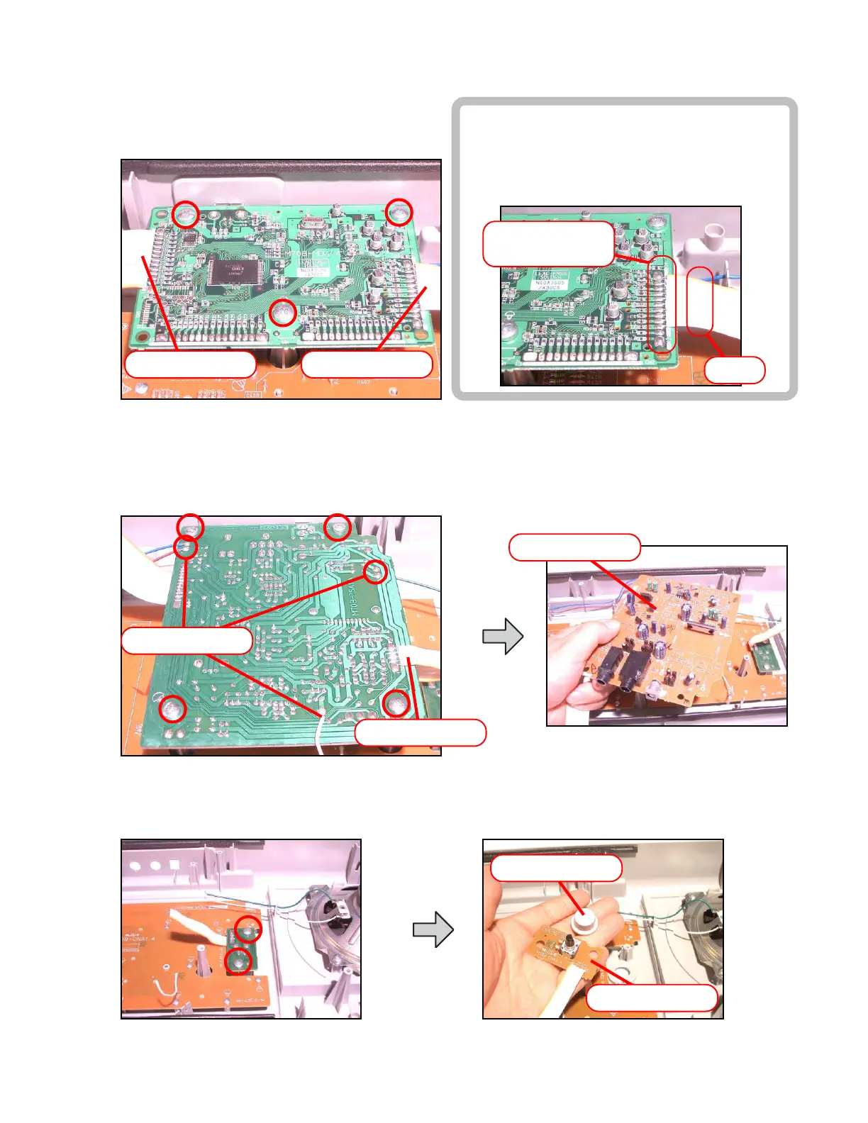
■ To remove the main PCB (M708-MDA1).
6. Remove three screws on the PCB (M708-MDA1).
7. Remove two connectors by soldering.
8. Remove the PCB (M708-MDA1).
■ To remove the sub PCB (M708-PSA1).
9. Remove four screws on the PCB (M708-PSA1).
10. Remove the connectors by soldering.
11. Remove five lead wires by soldering.
12. Remove the PCB (M708-PSA1).
Connector (CN4) Connector (CN1)
Connector (CN306)
Lead wires
M708-PSA1 PCB
■ To remove the console PCBs (M708-CNA1, CNA2).
13. Remove the volume knob.
14. Remove two screws on the PCB (M708-CNA2).
M708-CNA2 PCB
■ Precaution while assembling the main Connector 1.
Number of pins on the PCB and pins on the
cable are different.
Start connecting from the NO.1 pin whose color
is orange.
Connector (CN1)
12 pin
10 Pin
Knob
 Loading...